Leading manufacturer of photodetectors and distributed fiber optic sensing systems (DVS,DAS,DTS) from China, Over 100 universities and research units have chosen us.
Toggle navigation
Home
Products
Fiber Optic Sensing Module
DVS/DAS
Integration Module
DAQ
Data Acquisition Card
DTS
components
FBG
components
AOM
Acousto-optic modulator
EDFA
Erbium-Doped Fiber Amplifier
Optical Device
!!! DVS/DAS Product Introduction>>
Photodetector Module
PIN
Amplified Photodetector
APD
Avalanche Photodetector
DET
Biased Detectors
DMX
High-speed Photodetectors
BPD
Balanced Photodetector
chX
Multi-channel Photodetector
PD
Photodiodes
Light Source / Laser
Laser
Laser Module
UNL
-Narrow Linewidth Laser
PL
-Nanosecond Pulsed Laser
Amplifier
HCA
-Transimpedance Amplifier
Solutions
fiber optic sensing topics
Applications
Distributed Fiber Optic Sensing And Photodetectors Special Pages
3 Hardware Configurations for Building Distributed Fiber DAS Systems
DAS - Distributed Acoustic Sensing Topic Page
DTS - Distributed Temperature Sensing
BPD - Balanced photodetector
DVS - Distributed Fiber Optic Vibration Sensing
RADAR - Wind Measurement Radar
ROF
ROF Analog Optical Transmitter and Receiver
Case Studies
Technical Support
Documentation
Download Photodetector Specifications
DAS Module Selection Chart
Data Acquisition Card Product Selection Chart
Video Demonstration
About Us
About Us
Contact Us
Why Choose Us
R&D & Production Capabilities
Our Customers
Payment
Customs Declaration & Tariff Description
Estimated Delivery Time
Home
Products
Products
Photodetector Series
Fiber Optic Sensing System
Data Acquisition Card
Laser & Optical Components
PIN Amplified Photodetector
APD Photodetector
Balanced Photodetector
High-speed Photodetector
Multi-channel photodetector
Biased Detectors
Transimpedance Amplifier
Photodiodes
Distributed Acoustic Sensing DAS
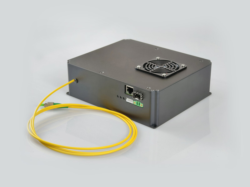
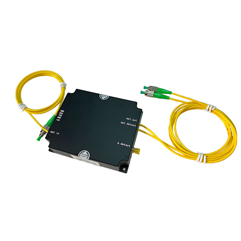
DVS/DAS Integrated Module
Narrow-Pulse DAS Module
Pulsed RF DAS Integration Module
Compact Distributed DAS All Demodulation Module
DTS Integrated Module
DAS Hardware All-in-One
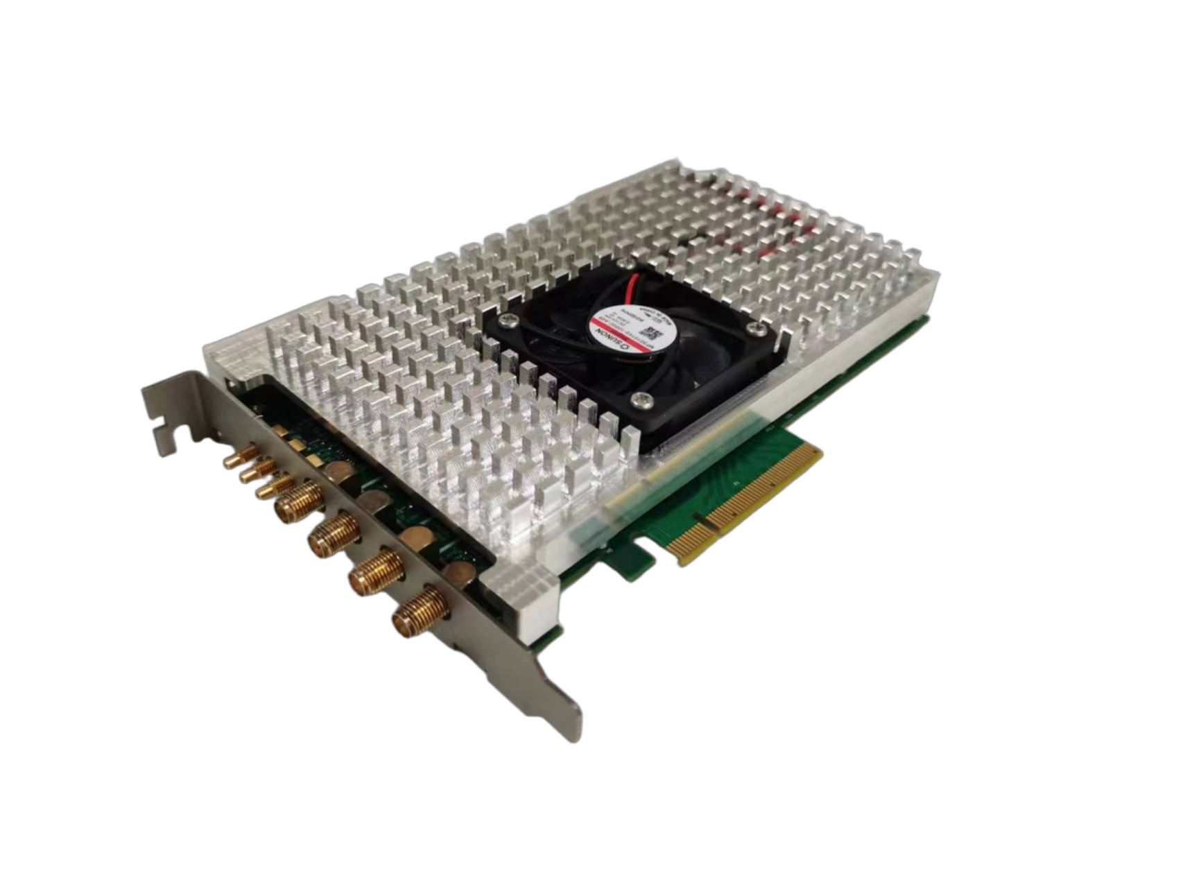
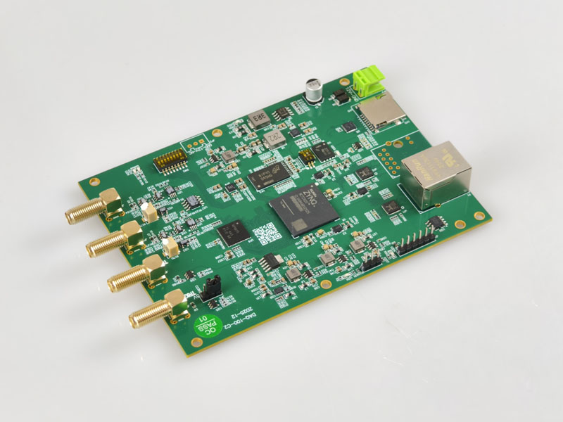
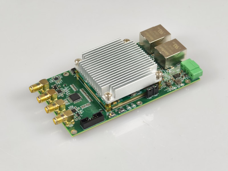
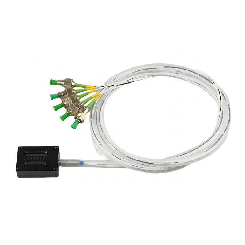
DAQ Boards
250M Ethernet & Optical Port Card
1G Sampling DAS Card
1G Chirp Sampling DAS Card
DTS Temperature Sensing Card
DAQ Board for DVS
DAQ50 Continuous Acquisition
Narrow Linewidth Laser
EDFA Fiber Amplifier
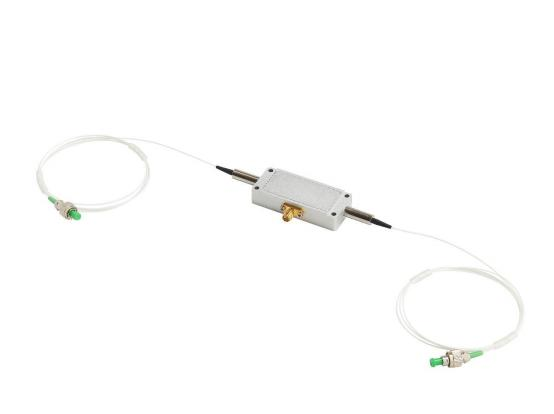
AOM Acousto-optic Modulator
Optical Switch Module