DVS/DAS Integrated Optical Module
The DVS/DAS Integrated Optical Module is internally designed with a coherent detection optical path for very high sensitivity and signal-to-noise ratio.
 Huang
Email: Hqy@ybphotonics.com
Huang
Email: Hqy@ybphotonics.com
 Download>>
Introduction
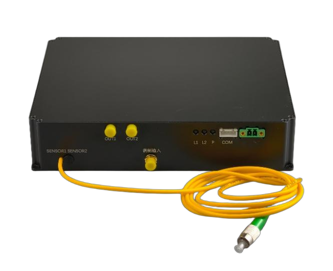
YB Photonics’s DVS/DAS integrated optical module highly integrates inside our own proprietary ultra-narrow linewidth laser, pulsed EDFA, Raman amplifier, AOM and other optical components in single compact package.
DAS/DVS integrated module integrates ultra-narrow linewidth light source, AOM acousto-optic modulator, AOM driver, pulsed EDFA, optical circulator, Raman amplifier, coherent receiver module, etc., which only needs to be paired with a high-speed data acquisition card to form a set of DAS Distributed Acoustic Wave (DVS Distributed Vibration) measurement system.
The module is highly integrated, small in size, and adopts independent intellectual property rights of coherent receiver module, which has the characteristics of high signal-to-noise ratio of coherent detection and increases the sensing distance of distributed fiber optic acoustic wave sensing system.
The module is specially designed for distributed fiber optic acoustic wave sensing, perimeter security equipment vendors to provide high-quality supporting products and solutions.
Current Latest Stable Version: V4.01
Key Parameters
We use this module with 250M sample rate DAQ card to realize the DAS system parameters (for reference)
Parameter Name
Parameter Value
Note
Maximum actual monitoring distance (without Raman)
≤40km
Refers to the correct frequency at which a single-frequency sound wave can be demodulated at the furthest end
Maximum actual monitoring distance (with Raman)
≤60km
Laser Pulsewidth
50ns-500ns
When using 80M AOM by default
Maximum time sampling resolution
4ns
Maximum sampling bandwidth of capture card with 250M sampling rate
Highest spatial sampling resolution
0.4m
Lower analog bandwidth limit for a single sensor at 40km
5Hz
Analog bandwidth limit for a single sensor at 40km
1000Hz
Range of spatial response to a single point of knock on the fiber at 40 km (i.e., the true spatial resolution of the system at the input of the shock function)
10m
Spatial positioning accuracy for a single point knock on the fiber at 40km
2m
Excitation at a point of the fiber, the monitoring system detects the positioning accuracy at the location of the excitation
What is the frequency accuracy of the sinusoidal input at 40km for a single point on the fiber with a length of 10 meters of fiber?
1Hz
Frequency range in which the excitation signal is received at the farthest end of the fiber and can be correctly demodulated at the longest monitoring distance
Integrated Device Parameters
Module parameters
Min. Type. Max. Unit Notes Measuring Distance
60 km pulse width
50 500 ns preheating time
<5 Min operating voltage
11.5 12 12.5 V Power 12 18 25 W operating temperature -20 60 ℃ Storage temperature -30 70 ℃ communications interface Serial TTL
communications protocol Modbus-RTU Ultra-narrow linewidth light source Min. Type. Max. Unit Notes operating wavelength
1550.12
nm output power 10 13 dBm line width <3 kHz relative intensity noise <120 dB/Hz wavelength drift ±1 pm power stability ±2% Side mode rejection ratio 60 dB Pulsed EDFA Min. Type. Max. Unit Notes Operating wavelength range 1550.12 nm Input peak optical power 10 dBm Input average optical power -35 -30 dBm Output peak optical power 23 dBm Output average optical power 0 dBm repetition rate 100 kHz coefficient of noise 5.5 dB Polarization Related Gain 0.5 dB polarization mode dispersion 0.5 ps AOM Min. Type. Max. Unit Notes Operating wavelength range 1520 1550 1580 nm Average optical power 0.5 W Maximum pulsed light power 0.5 kW insertion loss 2.5 3 dB extinction ratio 50 dB Rise/fall time 30 ns frequency 80 MHz standing wave ratio (physics) 1.2:1 Input Impedance 50 Ω RF power 2.5 W frequency shift 80 MHz customizable Balance detector Min. Type. Max. Unit Notes bandwidths
200 MHz gain (electronics) 50 kV/A NEP 30 pW/Sqrt(Hz)
Optical Path Structure
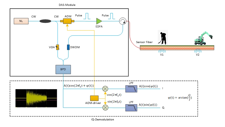
The DAS module is the optical path component of the DAS system, corresponding to the area enclosed by the solid black box in the figure above.The algorithm for the dotted boxes in the lower section is implemented in the capture card. Click here to view the capture card selection table.
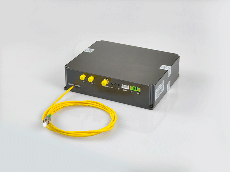
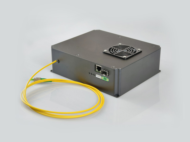
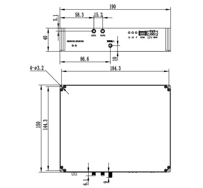
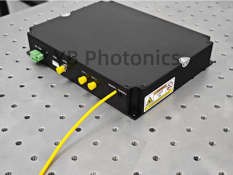
DAS Integrated Optical Module Mechanical Drawings
The following is a dimensional drawing of the DAS/DVS integrated module. The overall dimensions of the integrated module are 190 × 150 × 40 mm (excluding connectors and fiber optics). To ensure proper heat dissipation, ensure adequate ventilation when installing the module. When not in use, please cover the fiber optic flanges and coaxial connectors with their respective protective caps to prevent the connectors from becoming dirty.
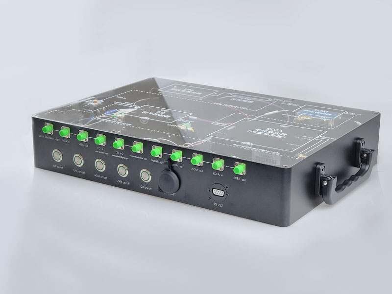
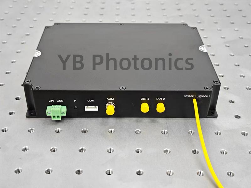
Interface Definitions
The DAS/DVS integration module interfaces are defined in the following table:
Interface Type Silkscreen Clarification Green Plug-in
Terminal
12V DC power supply +12V supply GND DC power supply GND White Plug-in
Terminal TTL Serial port, TTL level, communication with PC for parameter adjustment SMA modulation input AOM modulated signal input SMA
RF Input
Specialized for chirp models
Optical interface Sensor1 Sensing fiber 1, default FC/APC connector, single-channel products use this interface Optical interface Sensor2 Connect to sensing fiber 2, default FC/APC connector SMA OUT1 Module channel 1 output voltage signal, single-channel products use this interface SMA OUT2 Module channel 2 output voltage signal
Order Information
Mode No. Type Channels Distance
Intermediate Frequency
Laser linewidth
Features
GY-DAS-V4-40-1-A80 Single-mode standard type
1 ≤40km 80M <3kHz Great value for the price
GY-DAS-V4-40-2-A80
Single-mode standard type
2 ≤40km 80M <3kHz
Great value for the price
GY-DAS-V4-40-1-A200 Single-mode standard type
1 ≤40km 200M <3kHz
The spatial resolution can be increased
GY-DAS-V4-40-2-A200
Single-mode standard type
2 ≤40km
200M
<3kHz
The spatial resolution can be increased
GY-DAS-V4-60-1-A80
Single-mode standard type
1 ≤60km
80M <3kHz
Longer monitoring range
GY-DAS-V4-60-2-A80
Single-mode standard type
2 ≤60km
80M
<3kHz
Longer monitoring range
GY-DAS-V4-60-1-A200
Single-mode standard type
1 ≤60km
200M
<3kHz
Balancing spatial resolution and range
GY-DAS-V4-60-2-A200
Single-mode standard type
2 ≤60km
200M
<3kHz
Balancing spatial resolution and range
GY-DAS-V4-40-1-A80-1
Single-mode standard type
1 ≤40km
80M
<1kHz
The laser performs better
GY-DAS-V4-40-1-A200-1
Single-mode standard type
1 ≤40km
200M
<1kHz
The laser performs better
FAQ:Q:1、DVS and DAS, what is the difference between them?A: dvs is a qualitative measurement, detecting vibration by amplitude, but amplitude and vibration are not linear, das is phase demodulation, the demodulated phase is completely linear with vibration and can completely recover the vibration or sound signal. In YB Photonics modules, you need to specify DVS or DAS module when placing an order because there is a difference in the internal implementation of these two modules; the DVS module does the de-enveloping process after the BPD, while the DAS module outputs the signal from the BPD directly.
Q:3、Does the DAS Integration Module have an integrated capture card? What kind of capture card should I choose?
A:No, there is no integrated capture card in DAS integrated module, you need to buy DAS capture card separately. If you choose 80M AOM, then you can choose 250M sample rate capture card, if you choose 200M AOM, then you can choose 1G capture card.Unpacking and checking
Open the product box and check against the table below to make sure the following accessories are included, if any are missing, please contact us promptly.
Name Quantities DAS/DVS integrated module 1pcs 12V Power Module 1pcs USB to TTL Module 1pcs SMA RF Cable 3pcs Product Test Report 1pcs Certificate of Conformity 1pcs User's Manual 1pcs
Hardware Commissioning
Before starting to install the equipment, please be sure to read the "User Manual" carefully and follow the operating procedures specified in the "User Manual" to carry out installation and commissioning
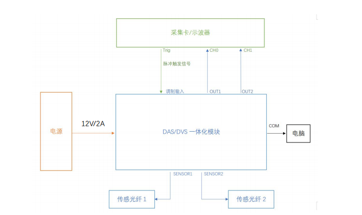
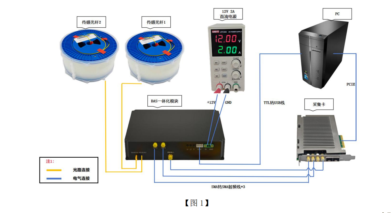
The test platform is shown in the figure below. Due to the high output optical power of the Sensor port (about 500mW), make sure that the Sensor port is connected to a sensing fiber or flange for attenuation before powering on the test platform, and do not look directly at the port with your eyes.
The whole module is connected to the sensing system, and the EDFA power, Raman amplifier power, and VOA value are adjusted through the serial port.
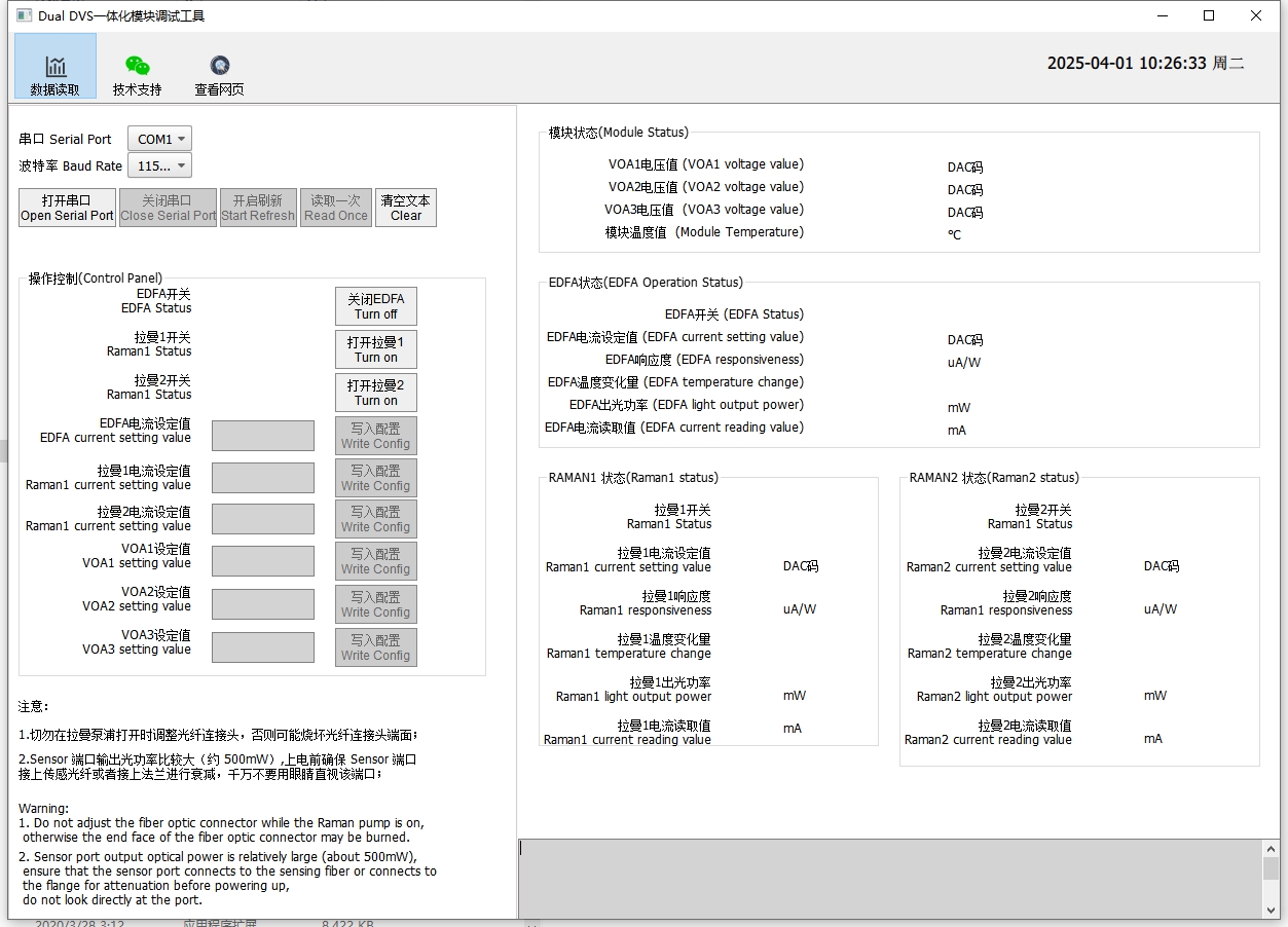
Control software for DAS modules
The DAS module is connected to the computer via a TTL-to-USB adapter cable. You can then use software on the computer to modify the operating parameters. Typically, we have already set these parameters to their optimal values before shipment, so under normal circumstances, there is no need to adjust them. See the detailed instructions for modifying operating parameters.
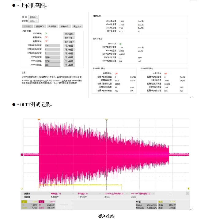
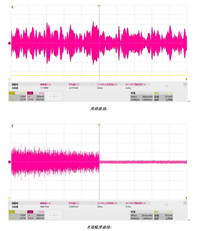
Test Screenshot
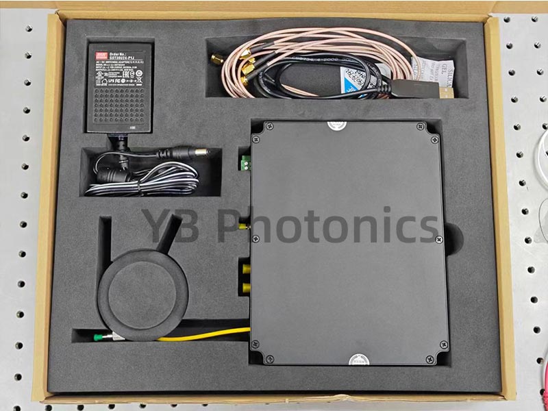
Shipment Packaging Pictures
YB Photonics’s DVS/DAS integrated optical module highly integrates inside our own proprietary ultra-narrow linewidth laser, pulsed EDFA, Raman amplifier, AOM and other optical components in single compact package.
DAS/DVS integrated module integrates ultra-narrow linewidth light source, AOM acousto-optic modulator, AOM driver, pulsed EDFA, optical circulator, Raman amplifier, coherent receiver module, etc., which only needs to be paired with a high-speed data acquisition card to form a set of DAS Distributed Acoustic Wave (DVS Distributed Vibration) measurement system.
The module is highly integrated, small in size, and adopts independent intellectual property rights of coherent receiver module, which has the characteristics of high signal-to-noise ratio of coherent detection and increases the sensing distance of distributed fiber optic acoustic wave sensing system.
The module is specially designed for distributed fiber optic acoustic wave sensing, perimeter security equipment vendors to provide high-quality supporting products and solutions.
Current Latest Stable Version: V4.01
Key Parameters
We use this module with 250M sample rate DAQ card to realize the DAS system parameters (for reference)
| Parameter Name | Parameter Value | Note |
|---|---|---|
| Maximum actual monitoring distance (without Raman) | ≤40km | Refers to the correct frequency at which a single-frequency sound wave can be demodulated at the furthest end |
| Maximum actual monitoring distance (with Raman) | ≤60km | |
| Laser Pulsewidth | 50ns-500ns | When using 80M AOM by default |
| Maximum time sampling resolution | 4ns | Maximum sampling bandwidth of capture card with 250M sampling rate |
| Highest spatial sampling resolution | 0.4m | |
| Lower analog bandwidth limit for a single sensor at 40km | 5Hz | |
| Analog bandwidth limit for a single sensor at 40km | 1000Hz | |
| Range of spatial response to a single point of knock on the fiber at 40 km (i.e., the true spatial resolution of the system at the input of the shock function) | 10m | |
| Spatial positioning accuracy for a single point knock on the fiber at 40km | 2m | Excitation at a point of the fiber, the monitoring system detects the positioning accuracy at the location of the excitation |
| What is the frequency accuracy of the sinusoidal input at 40km for a single point on the fiber with a length of 10 meters of fiber? | 1Hz | Frequency range in which the excitation signal is received at the farthest end of the fiber and can be correctly demodulated at the longest monitoring distance |
Integrated Device Parameters
| Module parameters | Min. | Type. | Max. | Unit | Notes |
|---|---|---|---|---|---|
| Measuring Distance | 60 | km | |||
| pulse width | 50 | 500 | ns | ||
| preheating time | <5 | Min | |||
| operating voltage | 11.5 | 12 | 12.5 | V | |
| Power | 12 | 18 | 25 | W | |
| operating temperature | -20 | 60 | ℃ | ||
| Storage temperature | -30 | 70 | ℃ | ||
| communications interface | Serial TTL | ||||
| communications protocol | Modbus-RTU | ||||
| Ultra-narrow linewidth light source | Min. | Type. | Max. | Unit | Notes |
| operating wavelength | 1550.12 | nm | |||
| output power | 10 | 13 | dBm | ||
| line width | <3 | kHz | |||
| relative intensity noise | <120 | dB/Hz | |||
| wavelength drift | ±1 | pm | |||
| power stability | ±2% | ||||
| Side mode rejection ratio | 60 | dB | |||
| Pulsed EDFA | Min. | Type. | Max. | Unit | Notes |
| Operating wavelength range | 1550.12 | nm | |||
| Input peak optical power | 10 | dBm | |||
| Input average optical power | -35 | -30 | dBm | ||
| Output peak optical power | 23 | dBm | |||
| Output average optical power | 0 | dBm | |||
| repetition rate | 100 | kHz | |||
| coefficient of noise | 5.5 | dB | |||
| Polarization Related Gain | 0.5 | dB | |||
| polarization mode dispersion | 0.5 | ps | |||
| AOM | Min. | Type. | Max. | Unit | Notes |
| Operating wavelength range | 1520 | 1550 | 1580 | nm | |
| Average optical power | 0.5 | W | |||
| Maximum pulsed light power | 0.5 | kW | |||
| insertion loss | 2.5 | 3 | dB | ||
| extinction ratio | 50 | dB | |||
| Rise/fall time | 30 | ns | |||
| frequency | 80 | MHz | |||
| standing wave ratio (physics) | 1.2:1 | ||||
| Input Impedance | 50 | Ω | |||
| RF power | 2.5 | W | |||
| frequency shift | 80 | MHz | customizable | ||
| Balance detector | Min. | Type. | Max. | Unit | Notes |
| bandwidths | 200 | MHz | |||
| gain (electronics) | 50 | kV/A | |||
| NEP | 30 | pW/Sqrt(Hz) | |||
Optical Path Structure
The DAS module is the optical path component of the DAS system, corresponding to the area enclosed by the solid black box in the figure above.The algorithm for the dotted boxes in the lower section is implemented in the capture card. Click here to view the capture card selection table.
DAS Integrated Optical Module Mechanical Drawings
The following is a dimensional drawing of the DAS/DVS integrated module. The overall dimensions of the integrated module are 190 × 150 × 40 mm (excluding connectors and fiber optics). To ensure proper heat dissipation, ensure adequate ventilation when installing the module. When not in use, please cover the fiber optic flanges and coaxial connectors with their respective protective caps to prevent the connectors from becoming dirty.
Interface Definitions
The DAS/DVS integration module interfaces are defined in the following table:
| Interface Type | Silkscreen | Clarification |
|---|---|---|
| Green Plug-in Terminal | 12V | DC power supply +12V supply |
| GND | DC power supply GND | |
| White Plug-in Terminal | TTL | Serial port, TTL level, communication with PC for parameter adjustment |
| SMA | modulation input | AOM modulated signal input |
| SMA | RF Input | Specialized for chirp models |
| Optical interface | Sensor1 | Sensing fiber 1, default FC/APC connector, single-channel products use this interface |
| Optical interface | Sensor2 | Connect to sensing fiber 2, default FC/APC connector |
| SMA | OUT1 | Module channel 1 output voltage signal, single-channel products use this interface |
| SMA | OUT2 | Module channel 2 output voltage signal |
Order Information
| Mode No. | Type | Channels | Distance | Intermediate Frequency | Laser linewidth | Features |
|---|---|---|---|---|---|---|
| GY-DAS-V4-40-1-A80 | Single-mode standard type | 1 | ≤40km | 80M | <3kHz | Great value for the price |
| GY-DAS-V4-40-2-A80 | Single-mode standard type | 2 | ≤40km | 80M | <3kHz | Great value for the price |
| GY-DAS-V4-40-1-A200 | Single-mode standard type | 1 | ≤40km | 200M | <3kHz | The spatial resolution can be increased |
| GY-DAS-V4-40-2-A200 | Single-mode standard type | 2 | ≤40km | 200M | <3kHz | The spatial resolution can be increased |
| GY-DAS-V4-60-1-A80 | Single-mode standard type | 1 | ≤60km | 80M | <3kHz | Longer monitoring range |
| GY-DAS-V4-60-2-A80 | Single-mode standard type | 2 | ≤60km | 80M | <3kHz | Longer monitoring range |
| GY-DAS-V4-60-1-A200 | Single-mode standard type | 1 | ≤60km | 200M | <3kHz | Balancing spatial resolution and range |
| GY-DAS-V4-60-2-A200 | Single-mode standard type | 2 | ≤60km | 200M | <3kHz | Balancing spatial resolution and range |
| GY-DAS-V4-40-1-A80-1 | Single-mode standard type | 1 | ≤40km | 80M | <1kHz | The laser performs better |
| GY-DAS-V4-40-1-A200-1 | Single-mode standard type | 1 | ≤40km | 200M | <1kHz | The laser performs better |
A: dvs is a qualitative measurement, detecting vibration by amplitude, but amplitude and vibration are not linear, das is phase demodulation, the demodulated phase is completely linear with vibration and can completely recover the vibration or sound signal. In YB Photonics modules, you need to specify DVS or DAS module when placing an order because there is a difference in the internal implementation of these two modules; the DVS module does the de-enveloping process after the BPD, while the DAS module outputs the signal from the BPD directly.
A:No, there is no integrated capture card in DAS integrated module, you need to buy DAS capture card separately. If you choose 80M AOM, then you can choose 250M sample rate capture card, if you choose 200M AOM, then you can choose 1G capture card.
Unpacking and checking
Open the product box and check against the table below to make sure the following accessories are included, if any are missing, please contact us promptly.
| Name | Quantities |
|---|---|
| DAS/DVS integrated module | 1pcs |
| 12V Power Module | 1pcs |
| USB to TTL Module | 1pcs |
| SMA RF Cable | 3pcs |
| Product Test Report | 1pcs |
| Certificate of Conformity | 1pcs |
| User's Manual | 1pcs |
Hardware Commissioning
Before starting to install the equipment, please be sure to read the "User Manual" carefully and follow the operating procedures specified in the "User Manual" to carry out installation and commissioning
The test platform is shown in the figure below. Due to the high output optical power of the Sensor port (about 500mW), make sure that the Sensor port is connected to a sensing fiber or flange for attenuation before powering on the test platform, and do not look directly at the port with your eyes.
The whole module is connected to the sensing system, and the EDFA power, Raman amplifier power, and VOA value are adjusted through the serial port.
Control software for DAS modules
The DAS module is connected to the computer via a TTL-to-USB adapter cable. You can then use software on the computer to modify the operating parameters. Typically, we have already set these parameters to their optimal values before shipment, so under normal circumstances, there is no need to adjust them. See the detailed instructions for modifying operating parameters.
Test Screenshot
Shipment Packaging Pictures
Product Related Videos
FAQ
-
Q: What is the lead time for your fiber optic sensing related module products?
A: Basically, we have more than 90% of modules in stock, only a few models need 2 weeks lead time. -
Q: Do you support the sale of those countries, and is the shipping included?
A: Our service is available worldwide, regardless of country or region. Shipping is included. -
Q: Who are your typical customers?
A: More than 100 top universities and research institutes in China have chosen us and given us high evaluations, such as: Chinese Academy of Sciences, CEC, Tsinghua University, Peking University and other clients.