fiber optic distributed temperature sensing (DTS) system components
Introduction
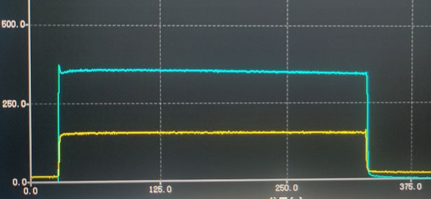
Distributed fiber optic temperature sensing systems (DTS) are currently based on the optical time domain reflection (OTDR) principle of optical fibers and the Raman scattering effect of optical fibers.Raman scattering is due to the thermal vibration of the fiber molecule, which produces a light longer than the wavelength of the light source - Stokes light - and a light shorter than the wavelength of the light source - Anti-Stokes light. The modulation of the fiber by the external temperature causes the Anti-Stokes light intensity in the fiber to change, and the ratio of Anti-Stokes to Stokes provides an absolute indication of the temperature.
| Module Components | Description |
|---|---|
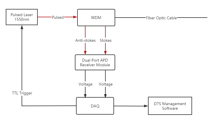
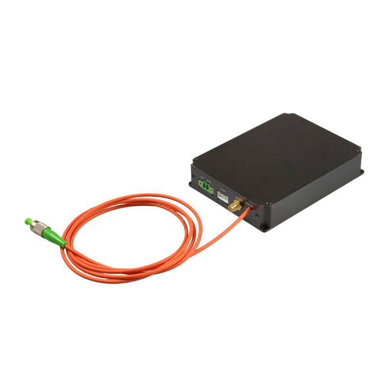
| 1550nm nanosecond pulsed laser for DTS | Used as a light source for DTS temperature measurement system, emitting pulsed laser with a typical pulse width of 10ns and supporting external trigger function |
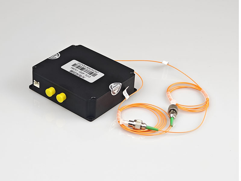
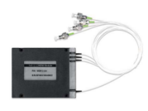
| 1x3 WDM coupler | WDM coupler mainly realize the coupling of the optical path, 4 ports, input port to connect the output of the pulse laser, COM interface to connect the sensing optical cable, and 2 ports to return Anti-Stokes and Stokes light, connected to 2 APD photodetector |
| Dual-channel APD photodetector | For detecting Anti-Stokes and Stokes light and converting the light signal into an electrical signal |
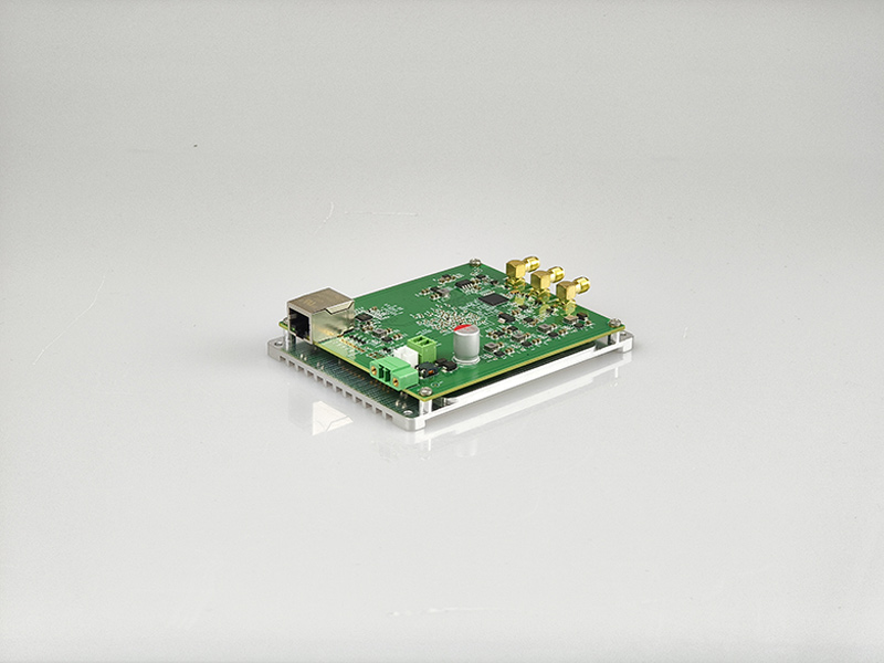
| DTS Data Acquisition Card | 200MSps sampling rate, built-in averaging algorithm, support pulse output |
DTS Hardware Component Module
How to demodulate fiber optic DTS temperature measurement system
Because the laser, photodetector performance parameters are different, as well as the selection of different fiber media, coupled with the increase in length of the temperature measurement fiber and more obvious attenuation and other issues, so there are also some researchers currently studying how to achieve high precision temperature demodulation algorithm. A common demodulation algorithm is as follows:
- Separate noise reduction for 2 signals
- Compensation operations on signals
- Get the value of Anti-Stokes and Stokes light signal: Analyze the value of Anti-Stokes and Stokes from the acquisition card
- Temperature calibration of ratio curves