GY-DAQ-2510D 1GSps Dual-Channel 14-bit High-Speed DAQ Card for DAS & LiDAR
The GY-DAQ-2510D is a 14-bit dual-channel high-speed DAQ card exclusively engineered for DAS fiber optic sensing and LiDAR systems. Boasting 1GSps synchronous trigger sampling, PCIe3.0 X8 high-speed interface (4GB/s transmission), and built-in coherent phase demodulation algorithm, it supports 100km+ DAS data acquisition with coherent fading suppression. With industrial-grade wide temperature stability and cross-platform compatibility, it is the ideal high-precision data acquisition solution for high-end coherent demodulation scenarios.
 Huang
Email: Hqy@ybphotonics.com
Huang
Email: Hqy@ybphotonics.com
Overview
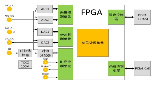
The GY-DAQ-2510D is a DAS/LiDAR dedicated high-precision data acquisition card designed for high-end coherent demodulation scenarios, equipped with on-board high-performance Kintex UltraScale (KU060) 20nm process FPGA and large-capacity data cache. Adopting high-speed data transmission engine technology, it realizes 4GB/s ultra-fast real-time data upload via PCIe3.0 X8 interface, meeting the large-volume, high-speed data collection needs of 100km+ long-distance DAS fiber optic sensing systems.
With dual-channel 14-bit high-speed ADC, the card achieves 1GSps synchronous trigger sampling and 66dBc SFDR, ensuring high signal-to-noise ratio and low distortion for weak coherent signals. Its built-in phase demodulation algorithm module realizes coherent fading suppression and global full-fiber demodulation — a key advantage over traditional IQ demodulation DAQ cards, greatly improving the accuracy and stability of demodulated signals and laying a solid foundation for subsequent signal processing and event identification.
The card features good driver compatibility, supporting multiple versions of Windows and Linux systems, and programmable in C/C++/Python/Matlab. It avoids complex phase unwrapping operations for users, reduces the host CPU computing power requirements, and greatly lowers the development difficulty of DAS/LiDAR systems, realizing simple and efficient data reading and phase vibration analysis.
API Documentation And Software Downloads
Key Advantages
- 1GSps Ultra-High-Speed Sampling
14-bit dual-channel synchronous trigger sampling, 5-250MHz analog bandwidth, 66dBc SFDR — captures ultra-high-precision signals for DAS/LiDAR.
- Built-in Coherent Phase Demodulation
Integrated coherent fading suppression & full-fiber demodulation, direct amplitude-phase data output — no secondary processing, reduces development difficulty.
- PCIe3.0 X8 High-Speed Transmission
4GB/s ultra-fast data transmission rate, large-capacity on-board cache — real-time uploading of demodulated data for large-scale DAS sensing (100km+).
- Multi-Resolution Customization
0.4m/0.8m/1.6m/3.2m/6.4m optional spatial resolution, 2-32 sampling gauge length — adapt to diverse DAS/LiDAR application requirements.
- Cross-Platform Compatibility
Supports Windows/Linux, programmable in C/C++/Python/Matlab — seamless integration with mainstream host systems, low OEM development cost.
- Industrial-Grade Wide Temperature Stability
-25℃~70℃ operating temperature, -40℃~85℃ storage temperature — reliable operation in harsh industrial and outdoor scenarios.
- AOM Modulation Compatibility
Supports 80MHz/200MHz AOM modulation — fully compatible with market mainstream DAS coherent demodulation modules.
System Block Diagram
Specifications
- 14bits dual channel synchronous real-time sampling
- 1G Sps sampling rate
- AC coupling, 50Ω input impedance
- 2.72 Vpp input voltage range,5 -250MHz analog bandwidth
- Up to66 dBc SFDR
- Trigger output pulse
- PCIe3.0 x8 high-speed transmission interface
- Built-in optical fiber sensing demodulation algorithm
Parameters
| resolution ratio | 14bit |
|---|---|
| sampling rate | 1GSps |
| number of channels | 2 |
| analog bandwidth | 250MHz |
| input range | 2.72Vpp |
| coupling mode | AC |
| impedance | 50Ω |
| SNR (Signal to NoiseRatio) | 66dBc SFDR |
| acquisition mode | triggered acquisition |
| trigger source | Internal trigger: 3.3V/5V TTL outputExternal trigger: 3.3V TTL input |
| demodulation algorithm | coherent fading suppression all-fiberdemodulation |
| intermediate frequency | 80MHz or 200MHz |
| resolution ratio | 0.4m, 0.8m, 1.6m, 3.2m, 6.4m optional |
| gauge length | 2-32 sampling site |
| transmission interface | PCIe3.0 X8 |
| transmission rate | 4GB/s |
| power supply | 12V 3A |
| power dissipation | <20W |
| operating temperature | -25℃-70℃ |
| storage temperature | -40℃-85℃ |
| programmingenvironment | C, C++, python, maltab, etc. |
| system platform | Windows 、Linux |
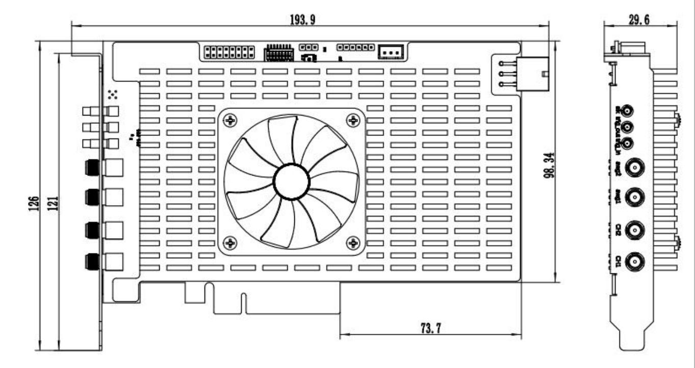
Interface Definition
- PCIe interface: for data transfer and parameter setting
- Ch1: Acquisition channel 1
- Ch2: Acquisition Channel 2
- Trig-in: External trigger, 3.3V input
- Trigger-out: Internal acquisition trigger output, 3.3V/5V optional
Ordering Information:
| model | describe | remark |
|---|---|---|
| GY-DAQ-2510D | 1G sampling rate full phase demodulationacquisition card | Support 80MAOMmodulation or 200MAOMmodulation |
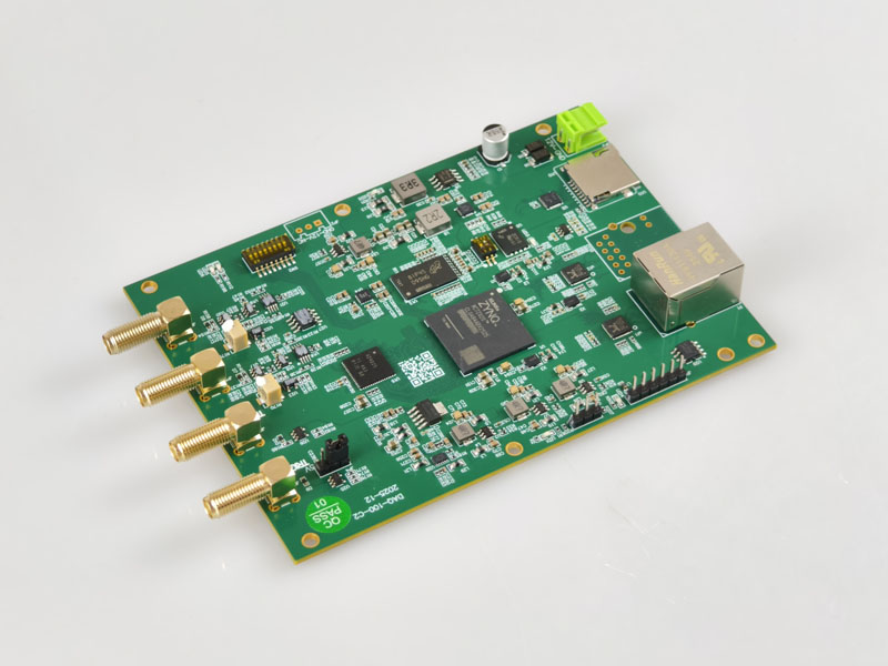
For use with the DAS module
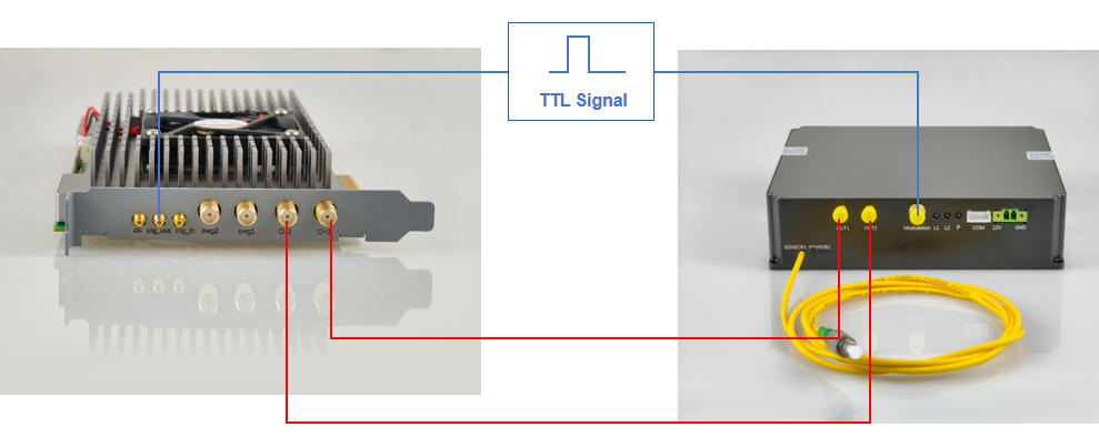
The GY-DAQ-2510D has a 1G sampling rate and can be used with a DAS system featuring a 200M intermediate frequency.
Interface Function Call Documentation
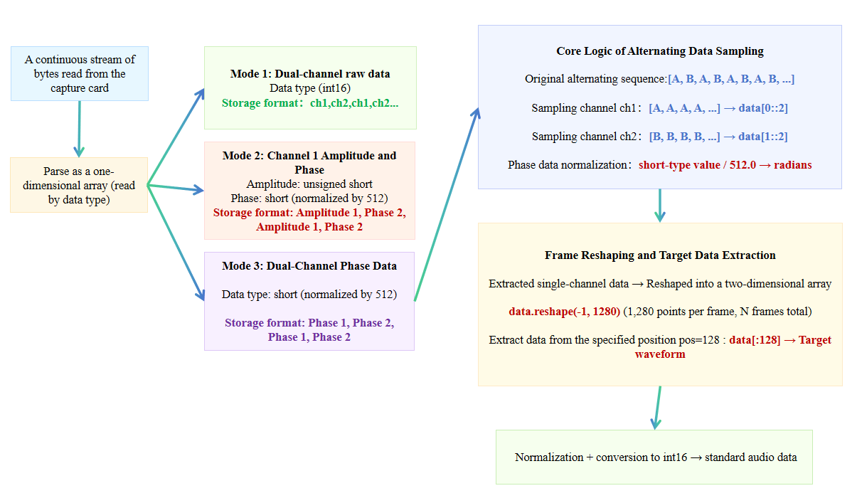
The GY-DAQ-2510D features built-in IQ demodulation and coherent fading suppression, making it suitable for DAS systems using coherent detection. It supports 80M AOM modulators or 200M AOM modulators, and supports both single-channel and dual-channel IQ demodulation, enabling real-time demodulation of the entire optical cable, where phase data represents vibration counts (audio data). The maximum number of data points uploaded per pulse trigger is 32,768; therefore, the maximum monitoring distances at different resolution rates are as follows:
0.4 m: 0.4 × 32,768 = 13,107.2 m
0.8 m: 0.8 × 32,768 = 26,214.4 m
1.6 m: 1.6 × 32,768 = 52,428.8 m
3.2 m: 3.2 × 32,768 = 104,857.6 m
To reduce the amount of uploaded data and achieve a greater monitoring distance, it is recommended to select a sampling resolution of 1.6 m or higher.
Reading and Parsing Data from a DAS Acquisition Card