Cost-Effective DAQ Boards For Distributed Acoustic Sensor DAS
DAS-specific data acquisition card with a 250 MHz sampling rate. Features built-in demodulation algorithms within the FPGA, enabling direct output of vibration signals without requiring additional demodulation on the PC for convenient operation.
 Huang
Email: Hqy@ybphotonics.com
Huang
Email: Hqy@ybphotonics.com
 Download>>
Introduction
Data Acquisition Card for Distributed Acoustic Fiber Sensing (DAS) with Pulse Output sends TTL pulses directly to the AOM driver, eliminating the need for an additional pulse generator and greatly reducing system complexity.
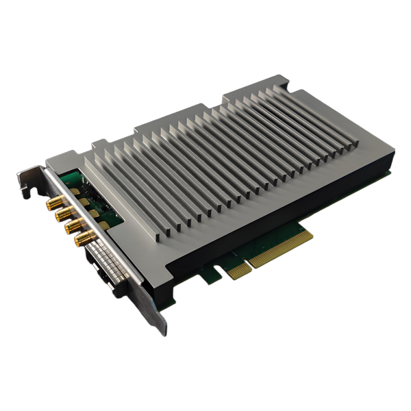
GY-DAQ-2480 as a DAS dedicated high-speed data acquisition card, using PCIe interface to communicate with the host computer, on-board high-performance FPGA chip, with rich multiplier and RAM resources. By adopting large-capacity data cache and high-speed data transmission engine technology, it supports real-time upload of original data, and the data transmission rate can reach 2.2GB/s. The acquisition card adopts dual-channel 14-bit high-speed ADC with sampling rate of 250MSps and supports DAS data acquisition of more than 100 km. Built-in phase demodulation algorithm, can directly upload amplitude phase demodulation data, phase data can be directly used by users as vibration signals, without demodulation processing again, to achieve full cable demodulation;or upload the original sampling data for users to demodulate. The driver has good compatibility, supports multiple versions of Windows and Linux, supports cross-platform use, and facilitates user integration.
Compared with the traditional IQ demodulation acquisition card, the acquisition card has a built-in phase demodulation algorithm module, which realizes coherent fading suppression and global demodulation, greatly improves the accuracy and stability of demodulated signals, and lays a foundation for subsequent signal processing and identification. It avoids the user still need to unwrap the operation after getting the data, reduces the system's requirements for CPU computing power, and also greatly reduces the user's development difficulty, realizing the simple operation of data reading and phase vibration.
API Documentation And Software Downloads
Parameters
Item Value Channel Number 2 Sampling Rate 250MSps Sampling Mode 14bits dual-channel synchronized real-time sampling Coupling Method DC-coupled Input Impedance 50Ω Input Voltage Range 2Vpp Bandwidth 0-100MHz analog bandwidth Settable Bias ±1V bias programmable to fully utilize ADC range SFDR Up to 88dBc Trigger Output Pulse Support PCIE PCIe2.0 x8 high-speed transmission interface Demodulation Algorithm Built-in fiber optic sensing demodulation algorithm
Power Supply and Power Consumption
- Power supply: 12V, 0.6A
- Power consumption: 12W (Max)
Temperature range
- Operating temperature: -20 ~ 60 ° C
- Storage temperature: -40~85°C
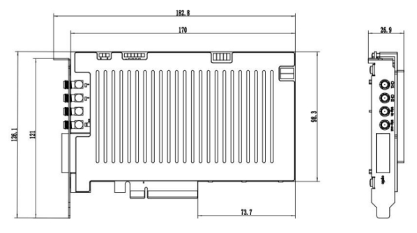
Mechanical Dimensions
- 182.8mm(L)x126mm(W)x26.9mm(D)
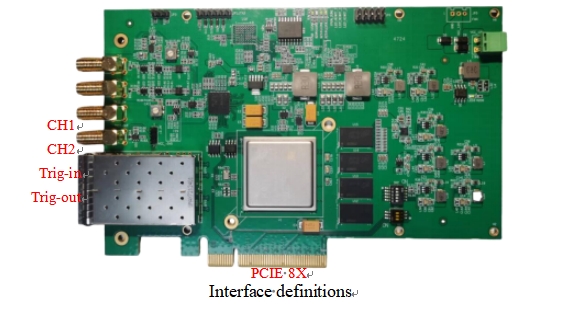
Interface definitions
- PCIe interface: for data transfer and parameter setting
- Ten thousand light ports: reserved
- Ch1: Acquisition channel 1
- Ch2: Acquisition Channel 2
- Trig-in: External trigger, 3.3V input
- Trigger-out: Internal acquisition trigger output, 3.3V/5V optional
How do I connect the DAS acquisition card (GY-DAQ-2480) to the DAS module?
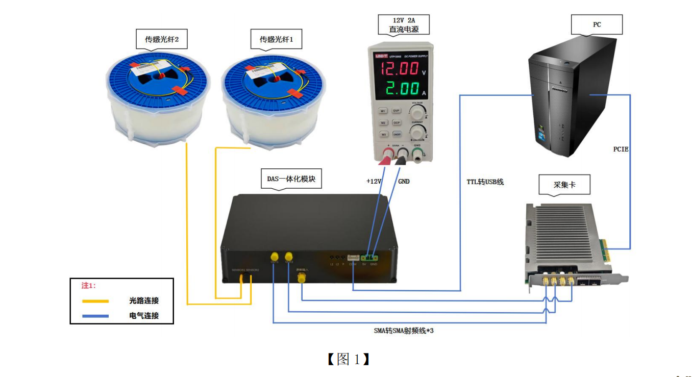
The DAS acquisition card (GY-DAQ-2480) uses a PCIe 2.0 x8 interface; simply insert it into a PCIe x8 or PCIe x16 slot on the computer, then connect it to the DAS module using a RF cable.
Test results
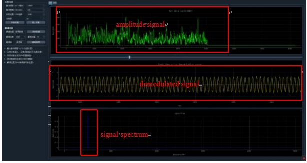
Raw signal curve
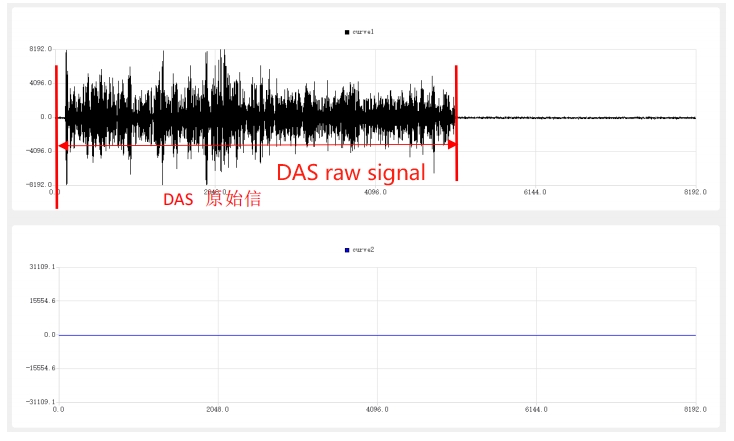
Amplitude-phase signal
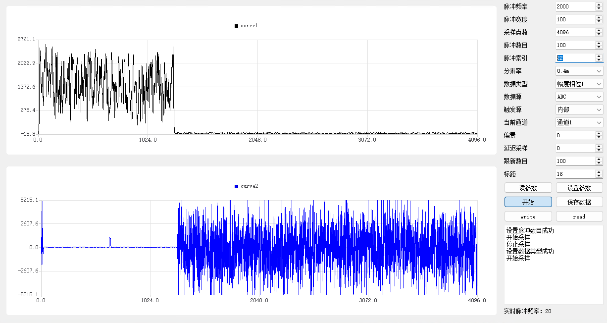
PZT single-frequency signal demodulation, restoring 500Hz sine excitation signals
Interface Function Call Description
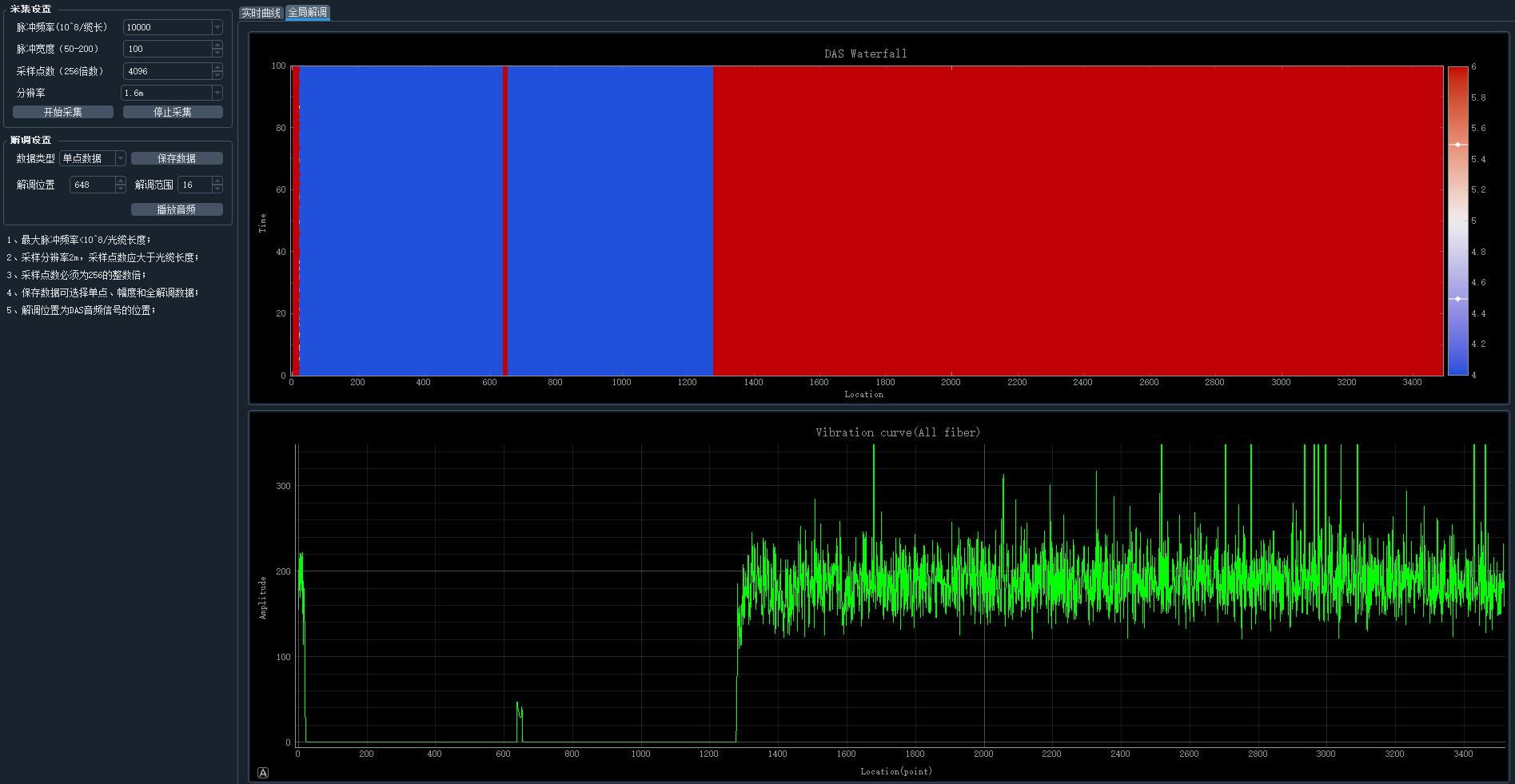
GY-DAQ-2480 has built-in IQ demodulation and coherent fading suppression functions, suitable for DAS systems with balanced detectors. It supports both single-channel IQ demodulation and dual-channel IQ demodulation to realize real-time demodulation of all optical cables. Phase data is vibration data (audio data). The maximum number of upload points per pulse trigger is 32768, so the maximum monitoring distance under different resolution rates is:
0.4m:0.4*32768=13107.2m
0.8m:0.8*32768=26214.4m
1.6m:1.6*32768=52428.8m
3.2m:3.2*32768=104857.6m
In order to reduce the amount of uploaded data and obtain a larger monitoring distance, it is suggested that the sampling resolution should be more than 1.6m.
API Interface Description
We provide the API in the form of a dynamic link library (.dll file) that you can call in your favorite programming language (e.g. python, C++, java or libview). Here is a description of the 2 more important functions.
int DasCardSetDataSel(int sel)
- Function description:
The board hasbuilt-in demodulationalgorithm, sel parameter is used to select the corresponding data type in the demodulation algorithm.
- Function parameter:
serial number sel value Upload Data Type parsing rules 1 1 Dual channel raw data ch1_data,ch2_data,ch1_data,ch2_data…… 2 2 Channel 1 Amplitude Phase Data |margin 1| Phase 1| margin 1| Phase 1|…… 3 3 Dual channel phase data |Phase 1| Phase 2| Phase 1| Phase 2|……
The original data and phase data are parsed as signed 16-bit integers (short), and the amplitude data is parsed as unsigned 16-bit integers (short); the phase datais signed 16-bit integers (short), which need to be divided by 512.0to be normalized to floating point numbers to correspond to radians. The phase data has been demodulated by all optical fibers and can be directly used as vibration data (audio data) for subsequent application development.
Related content
- Distributed Fiber Optic Vibration Sensing Module
- Distributed fiber optic acoustic sensing DAS module
- 100MSps high speed DAQ card for DVS
- Dual Port 250MSps High-Speed DAQ For DAS
- ultra-narrow linewidth 3k 1550nm laser
- Fiber optic vibration sensing DVS
- [Tutorial] How to wire the DVS/DAS system installation process?
- YB-DAS-250-DAQ Distributed Fiber Optic Vibration Data Acquisition Card Description
Data Acquisition Card for Distributed Acoustic Fiber Sensing (DAS) with Pulse Output sends TTL pulses directly to the AOM driver, eliminating the need for an additional pulse generator and greatly reducing system complexity.
GY-DAQ-2480 as a DAS dedicated high-speed data acquisition card, using PCIe interface to communicate with the host computer, on-board high-performance FPGA chip, with rich multiplier and RAM resources. By adopting large-capacity data cache and high-speed data transmission engine technology, it supports real-time upload of original data, and the data transmission rate can reach 2.2GB/s. The acquisition card adopts dual-channel 14-bit high-speed ADC with sampling rate of 250MSps and supports DAS data acquisition of more than 100 km. Built-in phase demodulation algorithm, can directly upload amplitude phase demodulation data, phase data can be directly used by users as vibration signals, without demodulation processing again, to achieve full cable demodulation;or upload the original sampling data for users to demodulate. The driver has good compatibility, supports multiple versions of Windows and Linux, supports cross-platform use, and facilitates user integration.
Compared with the traditional IQ demodulation acquisition card, the acquisition card has a built-in phase demodulation algorithm module, which realizes coherent fading suppression and global demodulation, greatly improves the accuracy and stability of demodulated signals, and lays a foundation for subsequent signal processing and identification. It avoids the user still need to unwrap the operation after getting the data, reduces the system's requirements for CPU computing power, and also greatly reduces the user's development difficulty, realizing the simple operation of data reading and phase vibration.
API Documentation And Software Downloads
Parameters
| Item | Value |
|---|---|
| Channel Number | 2 |
| Sampling Rate | 250MSps |
| Sampling Mode | 14bits dual-channel synchronized real-time sampling |
| Coupling Method | DC-coupled |
| Input Impedance | 50Ω |
| Input Voltage Range | 2Vpp |
| Bandwidth | 0-100MHz analog bandwidth |
| Settable Bias | ±1V bias programmable to fully utilize ADC range |
| SFDR | Up to 88dBc |
| Trigger Output Pulse | Support |
| PCIE | PCIe2.0 x8 high-speed transmission interface |
| Demodulation Algorithm | Built-in fiber optic sensing demodulation algorithm |
Power Supply and Power Consumption
- Power supply: 12V, 0.6A
- Power consumption: 12W (Max)
Temperature range
- Operating temperature: -20 ~ 60 ° C
- Storage temperature: -40~85°C
Mechanical Dimensions
- 182.8mm(L)x126mm(W)x26.9mm(D)
Interface definitions
- PCIe interface: for data transfer and parameter setting
- Ten thousand light ports: reserved
- Ch1: Acquisition channel 1
- Ch2: Acquisition Channel 2
- Trig-in: External trigger, 3.3V input
- Trigger-out: Internal acquisition trigger output, 3.3V/5V optional
How do I connect the DAS acquisition card (GY-DAQ-2480) to the DAS module?
The DAS acquisition card (GY-DAQ-2480) uses a PCIe 2.0 x8 interface; simply insert it into a PCIe x8 or PCIe x16 slot on the computer, then connect it to the DAS module using a RF cable.
Test results
Raw signal curve
Amplitude-phase signal
PZT single-frequency signal demodulation, restoring 500Hz sine excitation signals
Interface Function Call Description
GY-DAQ-2480 has built-in IQ demodulation and coherent fading suppression functions, suitable for DAS systems with balanced detectors. It supports both single-channel IQ demodulation and dual-channel IQ demodulation to realize real-time demodulation of all optical cables. Phase data is vibration data (audio data). The maximum number of upload points per pulse trigger is 32768, so the maximum monitoring distance under different resolution rates is:
0.4m:0.4*32768=13107.2m
0.8m:0.8*32768=26214.4m
1.6m:1.6*32768=52428.8m
3.2m:3.2*32768=104857.6m
In order to reduce the amount of uploaded data and obtain a larger monitoring distance, it is suggested that the sampling resolution should be more than 1.6m.
API Interface Description
We provide the API in the form of a dynamic link library (.dll file) that you can call in your favorite programming language (e.g. python, C++, java or libview). Here is a description of the 2 more important functions.
int DasCardSetDataSel(int sel)
- Function description:
The board hasbuilt-in demodulationalgorithm, sel parameter is used to select the corresponding data type in the demodulation algorithm.
- Function parameter:
| serial number | sel value | Upload Data Type | parsing rules |
|---|---|---|---|
| 1 | 1 | Dual channel raw data | ch1_data,ch2_data,ch1_data,ch2_data…… |
| 2 | 2 | Channel 1 Amplitude Phase Data | |margin 1| Phase 1| margin 1| Phase 1|…… |
| 3 | 3 | Dual channel phase data | |Phase 1| Phase 2| Phase 1| Phase 2|…… |
Related content
- Distributed Fiber Optic Vibration Sensing Module
- Distributed fiber optic acoustic sensing DAS module
- 100MSps high speed DAQ card for DVS
- Dual Port 250MSps High-Speed DAQ For DAS
- ultra-narrow linewidth 3k 1550nm laser
- Fiber optic vibration sensing DVS
- [Tutorial] How to wire the DVS/DAS system installation process?
- YB-DAS-250-DAQ Distributed Fiber Optic Vibration Data Acquisition Card Description