How to Wire a DAS Module
2023-05-30 22:52:20
Wiring diagram
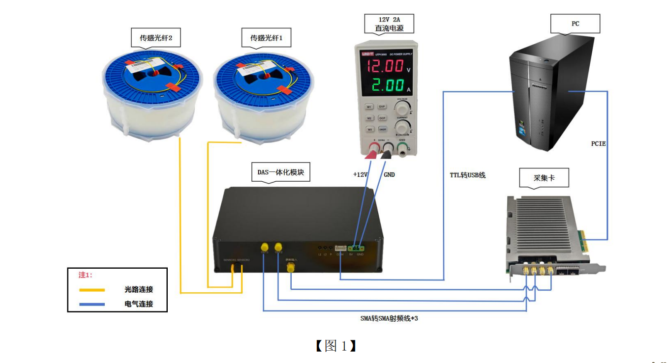
The above is a wiring diagram for the DAS module and the acquisition card.
Unboxing Photos of the DAS Module
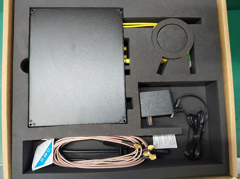
Unpacking and checking
Open the product box and check against the table below to make sure the following accessories are included, if any are missing, please contact us promptly.
| Name | Quantities |
|---|---|
| DAS/DVS integrated module | 1pcs |
| 12V Power Module | 1pcs |
| USB to TTL Module | 1pcs |
| SMA RF Cable | 3pcs |
| Product Test Report | 1pcs |
| Certificate of Conformity | 1pcs |
| User's Manual | 1pcs |
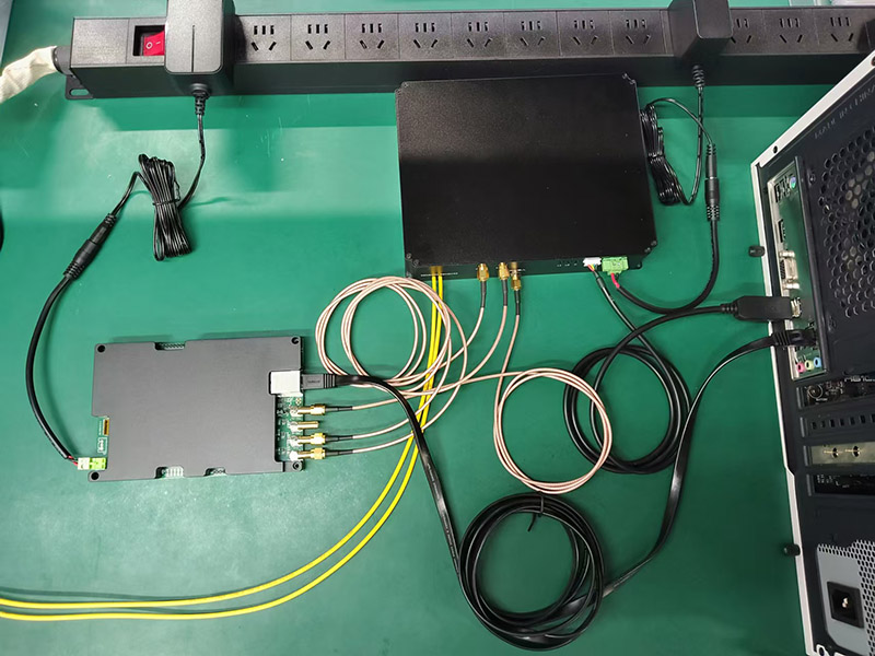
Actual Photos of the Wiring
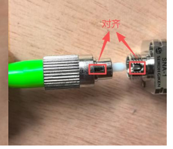
Precautions for Using FC/APC Connectors
FC/APC connectors are green, not black. Black connectors are FC/PC. We typically use FC/APC connectors in DAS systems.
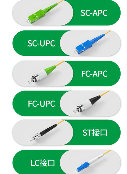
When connecting the FC/APC connectors, make sure to align the locking tabs.
Related Contents
Related Content
- DAS Module Selection Chart
- What type of fiber is used for distributed fiber optic vibration sensing?
- Component Configuration of a Distributed Fiber Optic Acoustic Sensing DAS
- Common Anomalous Signals in Distributed Acoustic Sensing (DAS) Systems and Their Handling
- What is the spatial resolution of the distributed fiber optic vibration monitoring system?
- What are the laser requirements for the DVS/DAS system?
- Difference Between DAS and DVS
- How to modify the operating parameters of a DAS module