DET30 bias photodetector ps-level pulse detection
The DET30 is a ready-to-use high-speed photodetector for use with FC-connected fiber optic cables in optical systems.
 Huang
Email: Hqy@ybphotonics.com
Huang
Email: Hqy@ybphotonics.com
 Download>>
Introduction
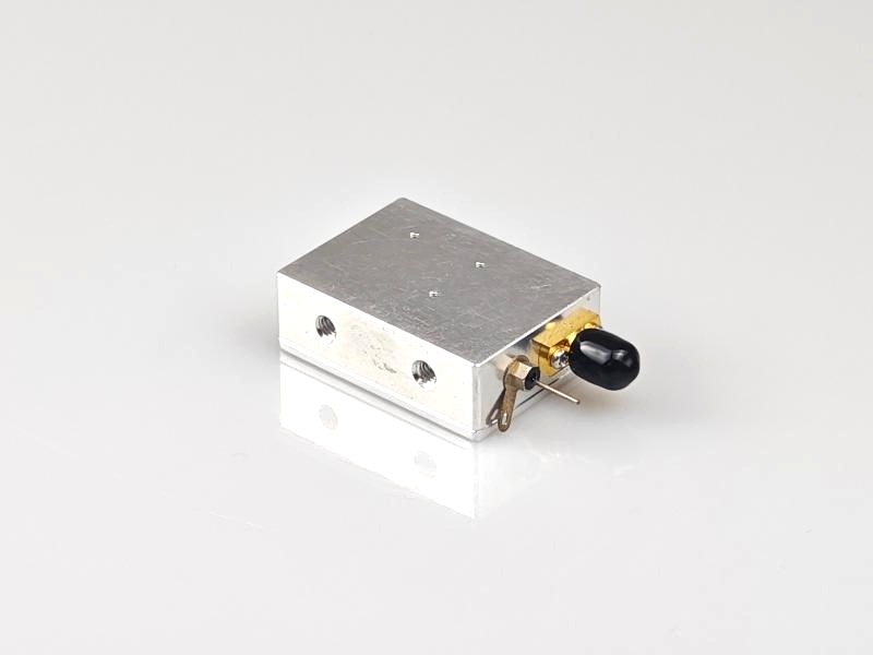
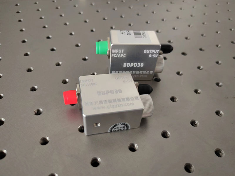
The DET30 bias photodetector is a compact, unamplified, fiber-optic input, battery-powered detector with very low noise, and can be used to detect optical signals with ps-level pulse widths.
1. Summarize
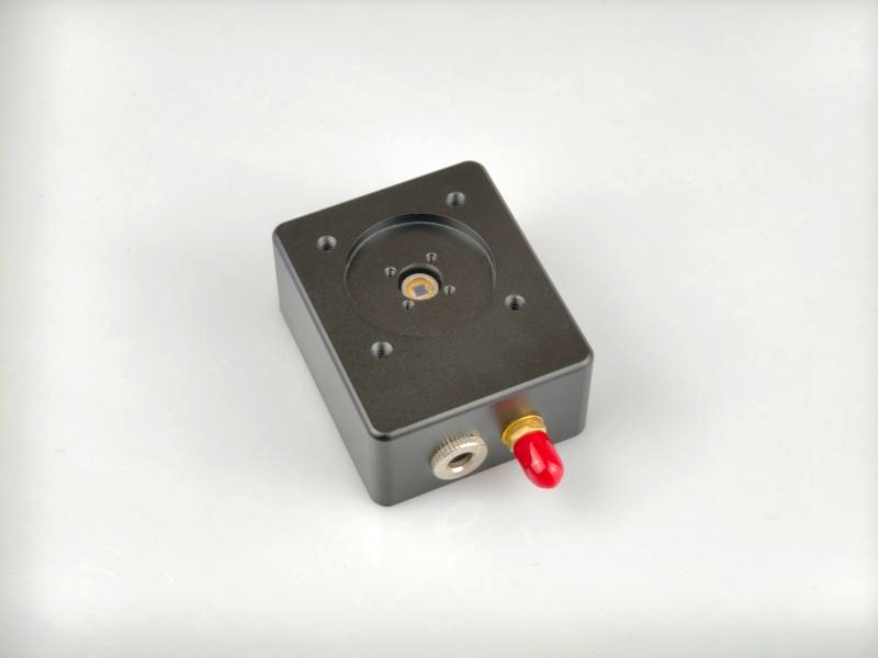
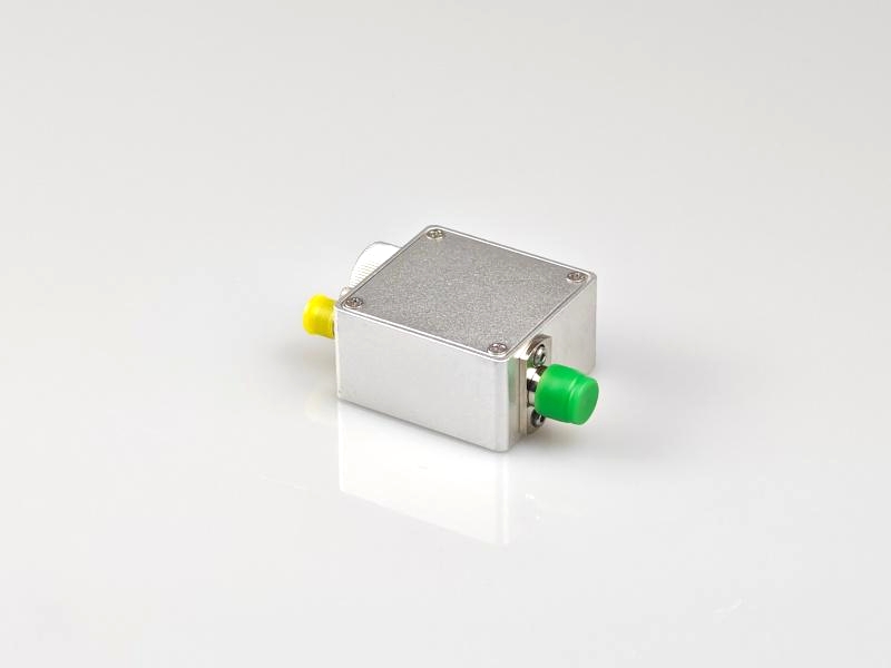
The DET30 is a ready-to-use high-speed photodetector for use with FC-connected fiber optic cables in optical systems. The unit consists of a circuit board, detector, RF connector, and 12V bias battery packaged in a compact aluminum enclosure.The FC flange facilitates coupling to a fiber optic light source, and an SMA connector is used at the output to reduce size and maximize frequency response up to a maximum bandwidth of 5 GHz.The detector is available in two spectral ranges, 400-1000 nm and 1000-1700 nm. 1700nm.
2. Product Features
- Four models covering the wavelength range of 400-1700nm
- Bandwidth from 1 to 5 GHz
- Rise time from 80ps to 350ps
- Connects to singlemode (SM) or multimode (MM) fibers
- FC fiber input connector
- SMA Output Connector
3. Applications
- Oscilloscope Optical Probe
- Laser Pulse Width Measurement
4. Specification parameters
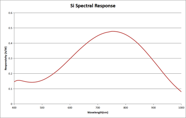
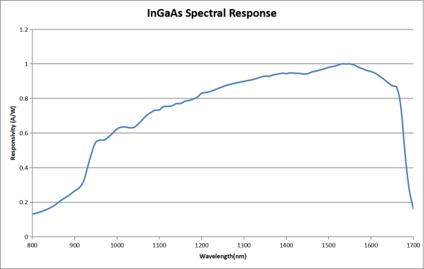
Item DET30A-1G DET30A-2G DET30C-2G DET30C-5G Material Si InGaAs Wavelenth 400-1000nm 1000-1700nm Active Area 200um 70um 70um 40um Peak Response 0.46A/W @850nm 0.90A/W @1550nm Bandwidth(a,b) DC-1GHz DC-2GHz DC-2GHz DC-5GHz Rise Time(a,b) 350ps 185ps 180ps 80ps Saturated optical power 5mW 5mW 5mW 4mW bias voltage 10V 10V 5V 5V Output impedance 50Ω Coupling mode DC output connector SMA female Operating temperature -10~65℃ Storage temperature -40~85℃
Remarks:
a:For 50Ω loads
b:Low battery voltage will result in slower rise time and lower bandwidth
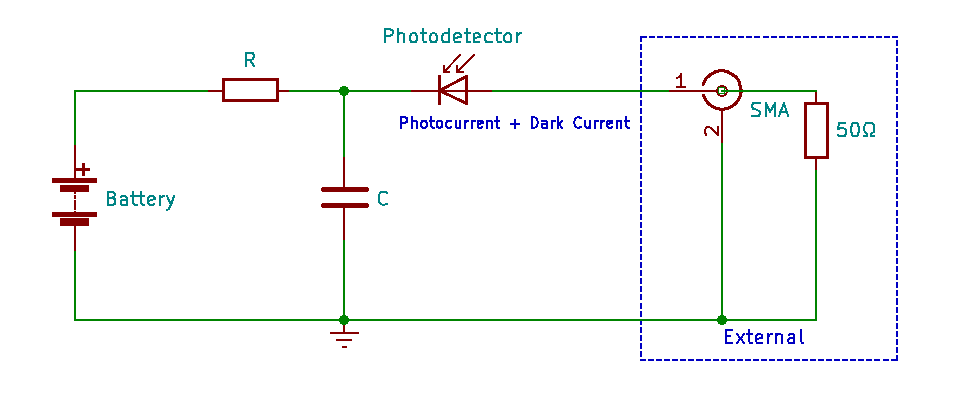
5. schematic
6. Operating Procedures
- Adjust the voltage grid of the oscilloscope to 10mV/div and set the input impedance of the oscilloscope to 50Ω;
- Connect the output of the detector to the input of the oscilloscope using coaxial cable;
- Clean the end of the fiber optic input connector, insert it into the detector FC flange and tighten it;
- Make sure that the power output from the laser source is within the saturation power of the detector, and then turn on the light source to be measured;
- Observe the waveform of the oscilloscope.
Note:
We use a load resistor R to convert the photocurrent I to a voltage V for viewing on an oscilloscope: V = I x R
Load resistance affects response speed, and for maximum bandwidth we recommend using a 50 ohm coaxial cable with a 50 ohm terminating resistor at the other end of the cable for impedance matching. If bandwidth is not important, the amount of voltage in a given light can be increased by gaining the load resistor. The length of the coaxial cable can have a profound effect on the response, so it is recommended to keep the cable as short as possible.
7. Battery life
Battery life is directly related to the amount of light power detected. Most battery manufacturers define battery life in mAh (milliampere hours). For example, the DET30 detector contains a battery that is 40 mAh. this means that it is capable of operating for 40 hours at 1.0 mA current. The following example illustrates how to determine the lifetime of this battery based on the optical power.
In this example, we incident a light source with an average power of 1 mW and a wavelength of 1550 nm onto an InGaAs detector. The response of the biased detector at this wavelength is 0.90 A/W and the photocurrent can be calculated according to the following equation:
I = 0.90A/W x 1mW = 0.9mA
The nominal battery life is 40 mAh, so the battery will continue to operate for:
T = 40mAh / 0.9mA = 44hr
When using the recommended 50 ohm termination resistor, the voltage corresponding to 1 mW of light is:
V = I x R = 0.9mA x 50 = 45mV
8. Replacement of batteries
The detector is powered by an A23 12V battery, first turn the battery cover counterclockwise to remove it, when installing a new battery, you need to pay attention to the positive and negative terminals of the battery, the negative terminal is the spring end of the battery cover. Remove the battery if it is not used for a long time.
9. Response curve
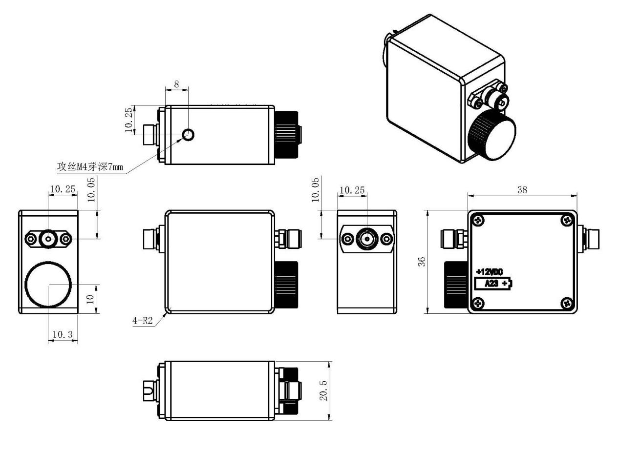
10. Mechanical dimensions
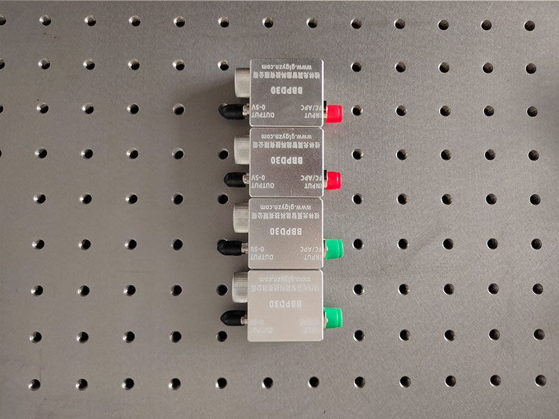
The DET30 bias photodetector is a compact, unamplified, fiber-optic input, battery-powered detector with very low noise, and can be used to detect optical signals with ps-level pulse widths.
1. Summarize
The DET30 is a ready-to-use high-speed photodetector for use with FC-connected fiber optic cables in optical systems. The unit consists of a circuit board, detector, RF connector, and 12V bias battery packaged in a compact aluminum enclosure.The FC flange facilitates coupling to a fiber optic light source, and an SMA connector is used at the output to reduce size and maximize frequency response up to a maximum bandwidth of 5 GHz.The detector is available in two spectral ranges, 400-1000 nm and 1000-1700 nm. 1700nm.
2. Product Features
- Four models covering the wavelength range of 400-1700nm
- Bandwidth from 1 to 5 GHz
- Rise time from 80ps to 350ps
- Connects to singlemode (SM) or multimode (MM) fibers
- FC fiber input connector
- SMA Output Connector
3. Applications
- Oscilloscope Optical Probe
- Laser Pulse Width Measurement
4. Specification parameters
| Item | DET30A-1G | DET30A-2G | DET30C-2G | DET30C-5G |
|---|---|---|---|---|
| Material | Si | InGaAs | ||
| Wavelenth | 400-1000nm | 1000-1700nm | ||
| Active Area | 200um | 70um | 70um | 40um |
| Peak Response | 0.46A/W @850nm | 0.90A/W @1550nm | ||
| Bandwidth(a,b) | DC-1GHz | DC-2GHz | DC-2GHz | DC-5GHz |
| Rise Time(a,b) | 350ps | 185ps | 180ps | 80ps |
| Saturated optical power | 5mW | 5mW | 5mW | 4mW |
| bias voltage | 10V | 10V | 5V | 5V |
| Output impedance | 50Ω | |||
| Coupling mode | DC | |||
| output connector | SMA female | |||
| Operating temperature | -10~65℃ | |||
| Storage temperature | -40~85℃ | |||
Remarks:
a:For 50Ω loads
b:Low battery voltage will result in slower rise time and lower bandwidth
5. schematic
6. Operating Procedures
- Adjust the voltage grid of the oscilloscope to 10mV/div and set the input impedance of the oscilloscope to 50Ω;
- Connect the output of the detector to the input of the oscilloscope using coaxial cable;
- Clean the end of the fiber optic input connector, insert it into the detector FC flange and tighten it;
- Make sure that the power output from the laser source is within the saturation power of the detector, and then turn on the light source to be measured;
- Observe the waveform of the oscilloscope.
Note:
We use a load resistor R to convert the photocurrent I to a voltage V for viewing on an oscilloscope: V = I x R
Load resistance affects response speed, and for maximum bandwidth we recommend using a 50 ohm coaxial cable with a 50 ohm terminating resistor at the other end of the cable for impedance matching. If bandwidth is not important, the amount of voltage in a given light can be increased by gaining the load resistor. The length of the coaxial cable can have a profound effect on the response, so it is recommended to keep the cable as short as possible.
7. Battery life
Battery life is directly related to the amount of light power detected. Most battery manufacturers define battery life in mAh (milliampere hours). For example, the DET30 detector contains a battery that is 40 mAh. this means that it is capable of operating for 40 hours at 1.0 mA current. The following example illustrates how to determine the lifetime of this battery based on the optical power.
In this example, we incident a light source with an average power of 1 mW and a wavelength of 1550 nm onto an InGaAs detector. The response of the biased detector at this wavelength is 0.90 A/W and the photocurrent can be calculated according to the following equation:
I = 0.90A/W x 1mW = 0.9mA
The nominal battery life is 40 mAh, so the battery will continue to operate for:
T = 40mAh / 0.9mA = 44hr
When using the recommended 50 ohm termination resistor, the voltage corresponding to 1 mW of light is:
V = I x R = 0.9mA x 50 = 45mV
8. Replacement of batteries
The detector is powered by an A23 12V battery, first turn the battery cover counterclockwise to remove it, when installing a new battery, you need to pay attention to the positive and negative terminals of the battery, the negative terminal is the spring end of the battery cover. Remove the battery if it is not used for a long time.
9. Response curve
10. Mechanical dimensions