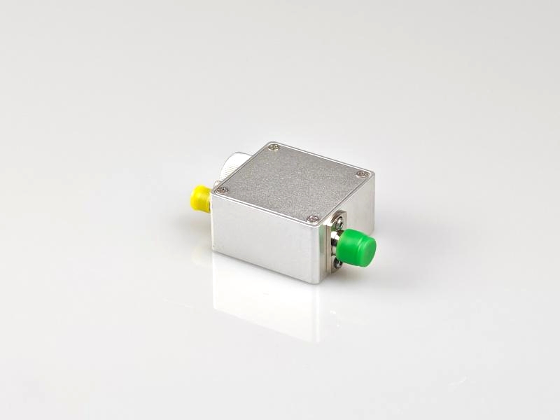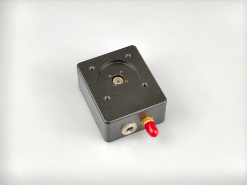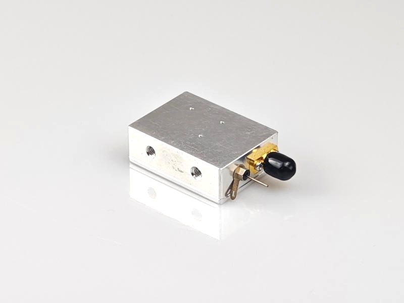
DET40 Free-Space Bias Photodetector
The DET40 is a ready-to-use, high-speed photodetector for free-space optical systems.
 Huang
Email: Hqy@ybphotonics.com
Huang
Email: Hqy@ybphotonics.com
 Download>>
1. Overview
The DET40 is a ready-to-use, high-speed photodetector for free-space optical systems. The unit consists of a circuit board, detector and RF connector in a compact aluminum housing. An SMA connector is used at the output to reduce size and maximize frequency response with a maximum bandwidth of 5 GHz.The detector is available in two spectral ranges, 320-1000 nm and 1000-1700 nm.
2. Features
- Five models cover the wavelength range 320-1700nm
- Bandwidth from 100MHz to 5GHz
- Rise times from 3.5ns to 350ps
- Compact size
3. Applications
- Analog Microwave
- Laser Pulse Width Measurement
4. Specifications
| Items | DET40A-100M | DET40A-500M | DET40A-1G | DET40C-2G | DET40C-5G |
|---|---|---|---|---|---|
| Materials | Si | InGaAs | |||
| Wavelength | 320-1000nm | 1000-1700nm | |||
| Photosensitive diameter | 1.2mm | 0.8mm | 0.4mm | 70um | 40um |
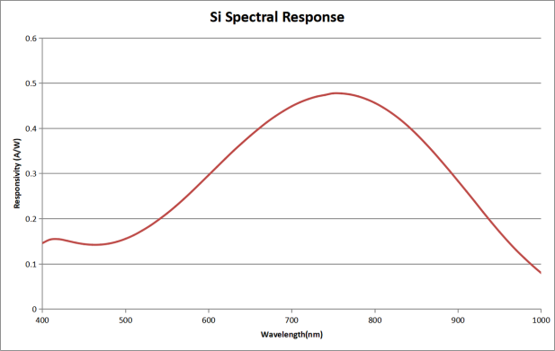
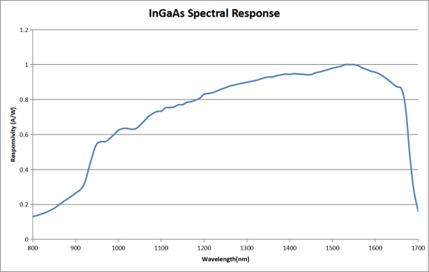
| Responsivity | 0.64A/W @920nm | 0.57A/W @800nm | 0.52A/W @760nm | 0.90A/W @1550nm | |
| Bandwidth (a) | DC-100MHz | DC-500MHz | DC-1GHz | DC-2GHz | DC-5GHz |
| Rise time (a) | 3.5ns | 0.8ns | 350ps | 180ps | 80ps |
| Damage threshold | 15mW | 15mW | 15mW | 5mW | 4mW |
| Bias voltage | 10V | 10V | 3.3V | 5V | 5V |
| Output Impedance | 50Ω | ||||
| Output coupling mode | DC | ||||
| output connector | SMA female | ||||
| Operating voltage | 12VDC | ||||
| Operating temperature | -20~65℃ | ||||
| Storage temperature | -40~85℃ | ||||
Remarks:
a For 50Ω load
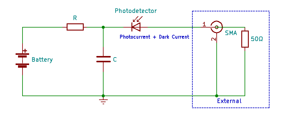
5. Schematic Block Diagram
6. Operating Procedures
- Adjust the voltage grid of the oscilloscope to 10mV/div and set the input impedance of the oscilloscope to 50Ω;
- Connect the output of the detector to the input of the oscilloscope with a coaxial cable;
- Ensure that the power received by the detector is within the saturation power, and then turn on the light source to be measured and align it with the photosensitive area;
- Observe the waveform of the oscilloscope.
Note: We use a load resistor R to convert the photocurrent I to a voltage V for viewing on an oscilloscope: V = I x R
Load resistance affects response speed, and for maximum bandwidth we recommend using a 50 ohm coaxial cable with a 50 ohm terminating resistor at the other end of the cable for impedance matching. If bandwidth is not important, the amount of voltage in a given light can be increased by gaining the load resistor. The length of the coaxial cable can have a profound effect on the response, so it is recommended to keep the cable as short as possible.
7. Response curve
8. Mechanical dimensions
41x30x14mm(Without connectors)
9. Shipping list
| Item | Name of material | num | unit | note |
|---|---|---|---|---|
| 1 | photodetector | 1 | pcs | |
| 2 | SMA to BNC RF Cable | 2 | pcs |