Bias photodetector, free space light for mW level optical power detection
DET20 series bias photodetector for mW level optical power detection, using free space light input.
 Huang
Email: Hqy@ybphotonics.com
Huang
Email: Hqy@ybphotonics.com
 Download>>
Introduction
DET20 series bias photodetector for mW level optical power detection, using free space light input, the series of photodetectors without amplification circuit, with very low noise, the module using analog signal output.
1. Overview
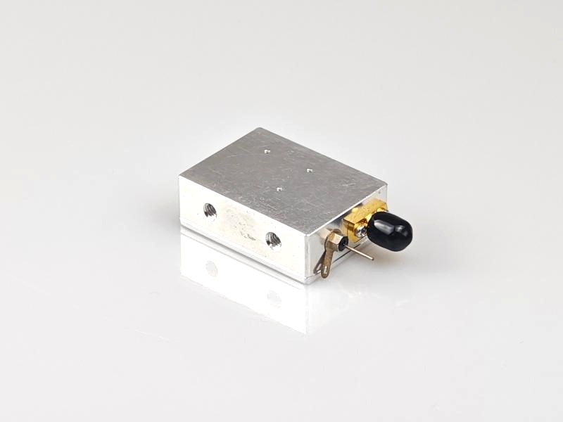
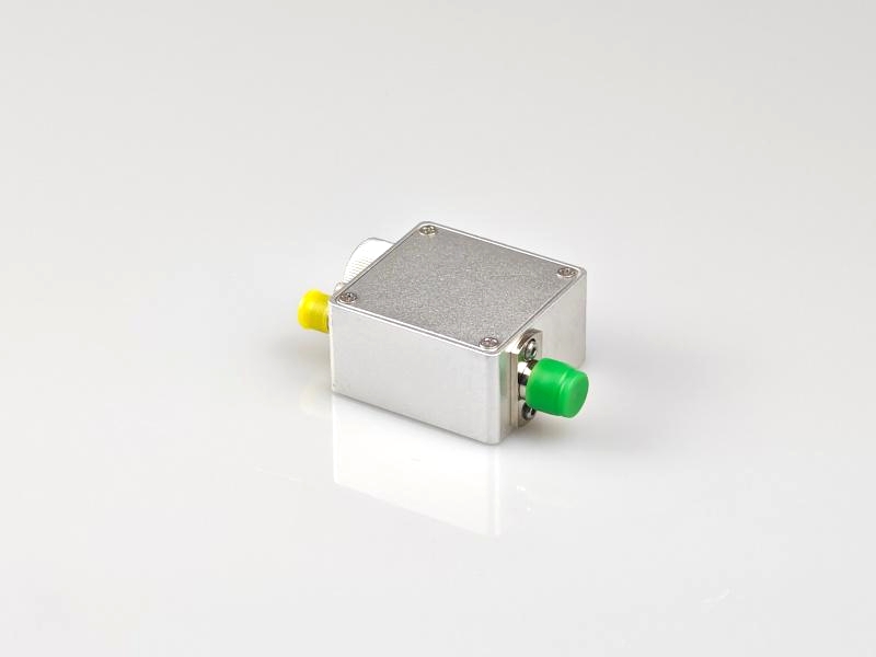
The DET20 is a ready-to-use photodetector for free-space optical systems. The unit consists of a circuit board, detector and RF connector packaged in a compact aluminum housing. An SMA connector is used at the output to reduce size and maximize frequency response.
2. Features
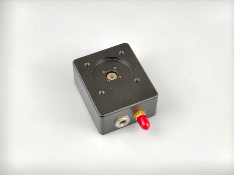
- 30mm mounting holes for optical cage system
- Large optical size
- Optional lithium battery power supply, lower noise
- Optional FC flange, can use fiber optic coupling
3. Applications
- Optical experiment
- Pulsed light waveform detection
- Measuring Instruments
4. Specifications
Items DET20A-20M Materials Si Wavelength 320-1000nm Active Area 3.6x3.6mm Responsivity 0.6A/W @960nm Bandwidth (a) DC-20MHz Rise time (a) 18ns Damage threshold 30mW Bias voltage 10V Output Impedance 50Ω Output coupling mode DC output connector SMA female Operating voltage 12VDC Operating temperature -20~65℃ Storage temperature -40~85℃
Remarks:
a For 50Ω load
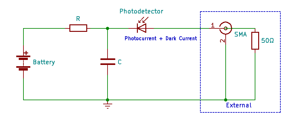
5. Schematic Block Diagram
6. Operating Procedures
- Adjust the voltage grid of the oscilloscope to 10mV/div and set the input impedance of the oscilloscope to 50Ω;
- Connect the output of the detector to the input of the oscilloscope with a coaxial cable;
- Ensure that the power received by the detector is within the saturation power, and then turn on the light source to be measured and align it with the photosensitive area;
- Observe the waveform of the oscilloscope.
Note: We use a load resistor R to convert the photocurrent I to a voltage V for viewing on an oscilloscope: V = I x R
Load resistance affects response speed, and for maximum bandwidth we recommend using a 50 ohm coaxial cable with a 50 ohm terminating resistor at the other end of the cable for impedance matching. If bandwidth is not important, the amount of voltage in a given light can be increased by gaining the load resistor. The length of the coaxial cable can have a profound effect on the response, so it is recommended to keep the cable as short as possible.
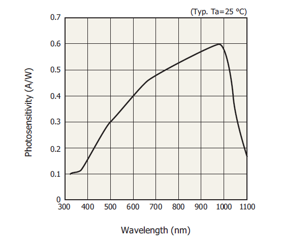
7. Response curve
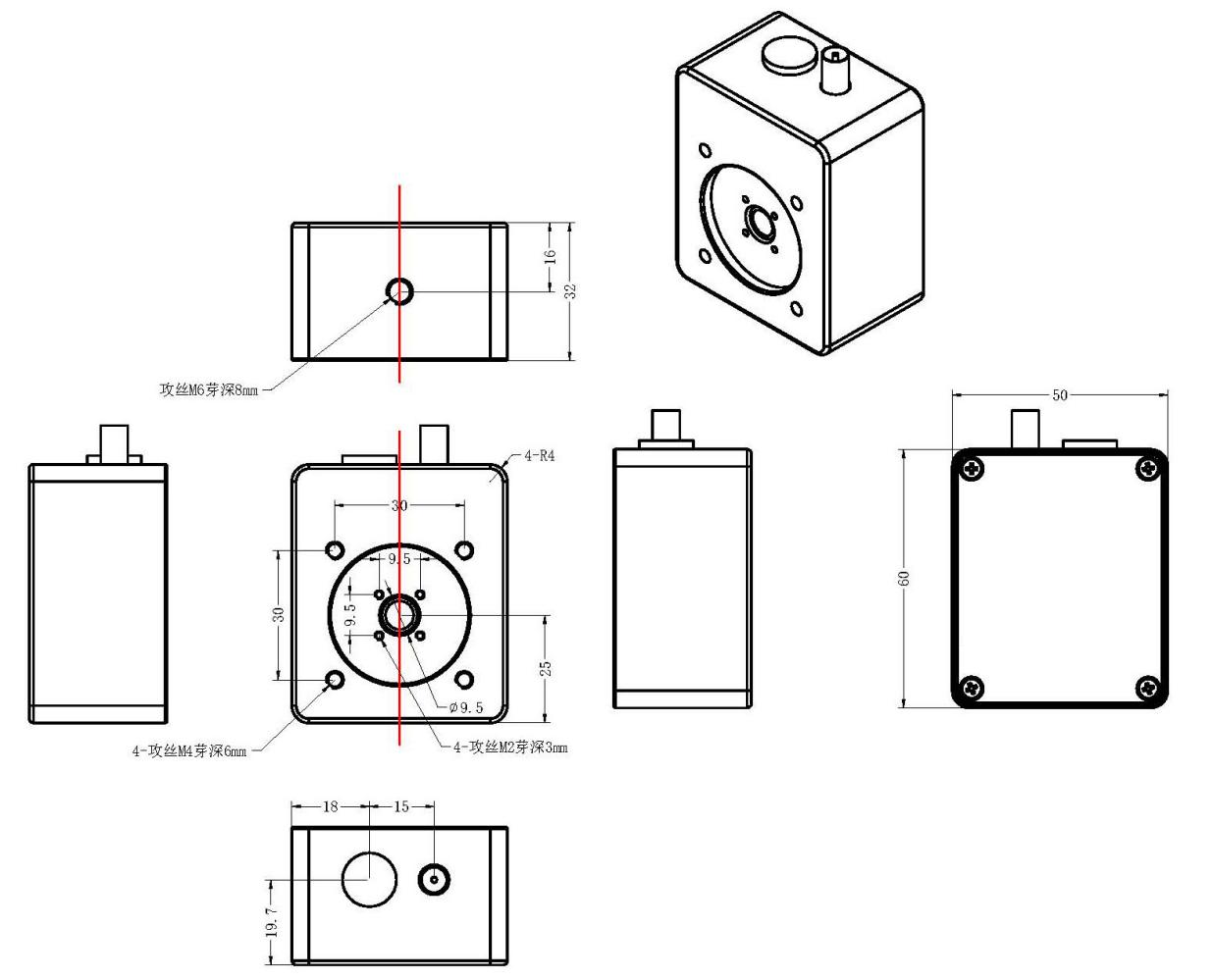
8. Mechanical dimensions
9. Shipping list
Item Name of material num unit note 1 photodetector 1 pcs 2 power adapter 1 Pcs 12V 3 SMA to BNC RF Cable 2 pcs
DET20 series bias photodetector for mW level optical power detection, using free space light input, the series of photodetectors without amplification circuit, with very low noise, the module using analog signal output.
1. Overview
The DET20 is a ready-to-use photodetector for free-space optical systems. The unit consists of a circuit board, detector and RF connector packaged in a compact aluminum housing. An SMA connector is used at the output to reduce size and maximize frequency response.
2. Features
- 30mm mounting holes for optical cage system
- Large optical size
- Optional lithium battery power supply, lower noise
- Optional FC flange, can use fiber optic coupling
3. Applications
- Optical experiment
- Pulsed light waveform detection
- Measuring Instruments
4. Specifications
| Items | DET20A-20M |
|---|---|
| Materials | Si |
| Wavelength | 320-1000nm |
| Active Area | 3.6x3.6mm |
| Responsivity | 0.6A/W @960nm |
| Bandwidth (a) | DC-20MHz |
| Rise time (a) | 18ns |
| Damage threshold | 30mW |
| Bias voltage | 10V |
| Output Impedance | 50Ω |
| Output coupling mode | DC |
| output connector | SMA female |
| Operating voltage | 12VDC |
| Operating temperature | -20~65℃ |
| Storage temperature | -40~85℃ |
Remarks:
a For 50Ω load
5. Schematic Block Diagram
6. Operating Procedures
- Adjust the voltage grid of the oscilloscope to 10mV/div and set the input impedance of the oscilloscope to 50Ω;
- Connect the output of the detector to the input of the oscilloscope with a coaxial cable;
- Ensure that the power received by the detector is within the saturation power, and then turn on the light source to be measured and align it with the photosensitive area;
- Observe the waveform of the oscilloscope.
Note: We use a load resistor R to convert the photocurrent I to a voltage V for viewing on an oscilloscope: V = I x R
Load resistance affects response speed, and for maximum bandwidth we recommend using a 50 ohm coaxial cable with a 50 ohm terminating resistor at the other end of the cable for impedance matching. If bandwidth is not important, the amount of voltage in a given light can be increased by gaining the load resistor. The length of the coaxial cable can have a profound effect on the response, so it is recommended to keep the cable as short as possible.
7. Response curve
8. Mechanical dimensions
9. Shipping list
| Item | Name of material | num | unit | note |
|---|---|---|---|---|
| 1 | photodetector | 1 | pcs | |
| 2 | power adapter | 1 | Pcs | 12V |
| 3 | SMA to BNC RF Cable | 2 | pcs |