How to Connect the GY-DAQ-2480 to a DAS Module
2026-06-14 12:56:10
1. PCIe Interface
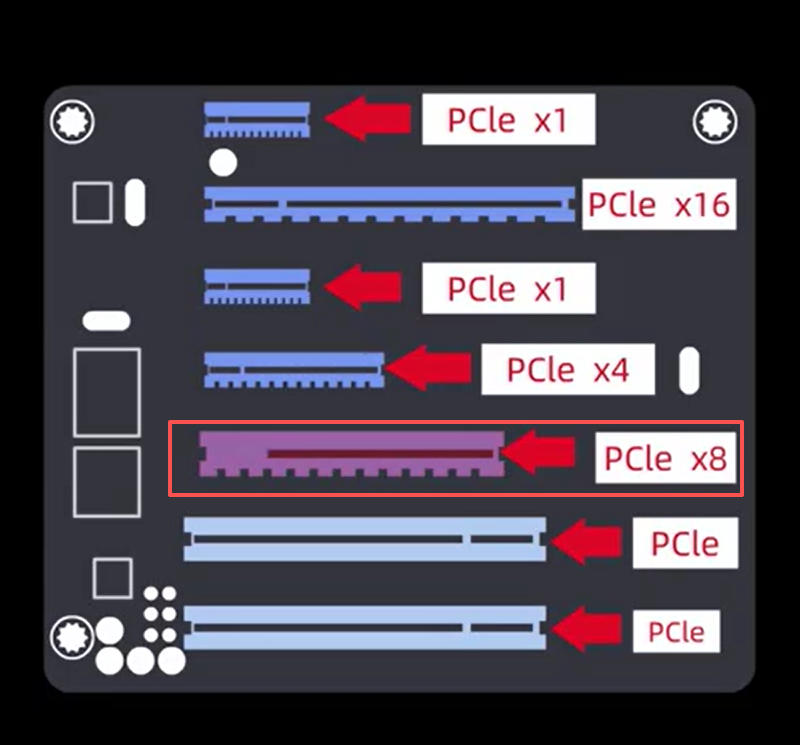
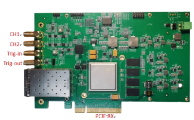
The GY-DAQ-2480 uses a PCIe interface to communicate with the host computer. First, you will need a computer that supports PCIe x8; insert the data acquisition card into the PCIe x8 slot on the computer’s motherboard.
After inserting the data acquisition card, install the drivers on the computer by following the driver installation instructions.
https://www.ybphotonics.com/doc/documents/58
2. DAQ Port
The DAQ card has four ports: CH0 and CH1, which indicate that data can be acquired from two channels;Trig is the trigger output interface; CLK is the clock synchronization interface.
3. Power Supply
The integrated Distributed Acoustic Sensing (DAS) module operates at 12V. If you do not have a compatible power supply module, you may contact us for supporting model recommendations.
4. Wiring Connections
DAS integrated module; from left to right: OUT1 indicates the output for Channel 1; OUT2 indicates the output for Channel 2. Next are two sensor fiber optic ports: Sensor1 corresponds to Channel 1, and Sensor2 corresponds to Channel 2.
For a single-channel system, simply connect the OUT1 port to the CH1 port on the acquisition card using an RF cable.
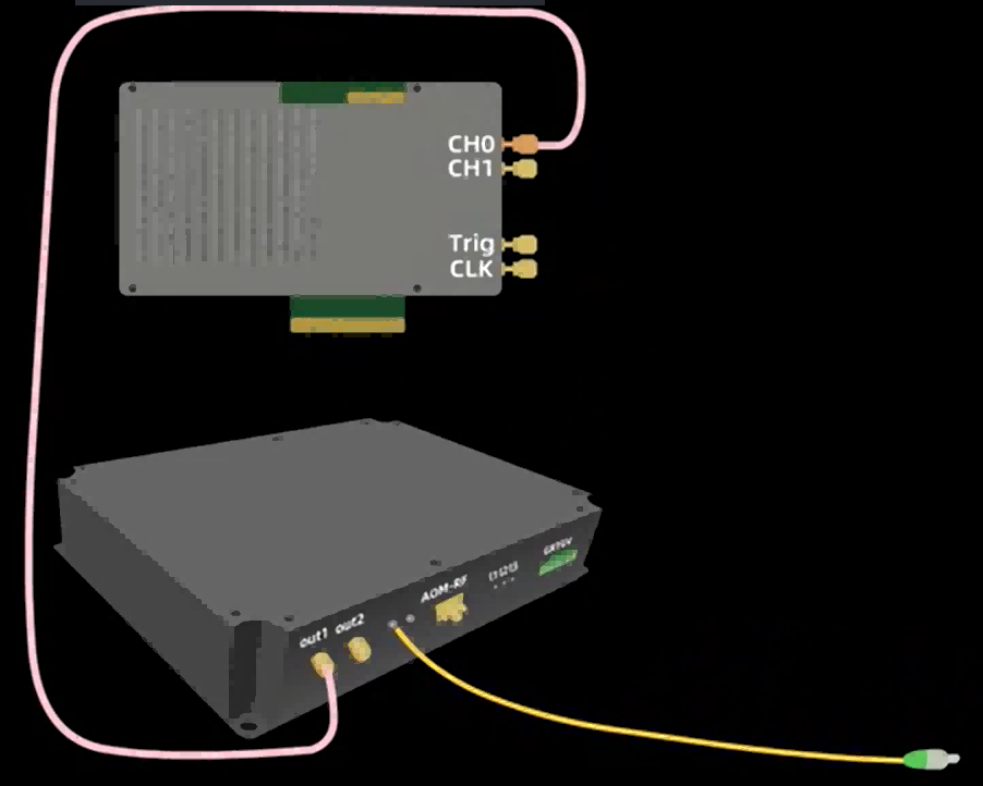
The acoustic-optical modulator also has one RF input port and one RF output port. The RF input port is connected to the data acquisition card’s Trig trigger output port via an RF cable; the RF output port is connected to the DAS integrated module’s AOM RF port via an RF cable.
At this point, the connection to the data acquisition card is complete. Connect the DAS module to the sensor fiber optic cable, verify that all connections are correct, and then power on the system for testing.
Related Content
- Data Acquisition Card Documentation Downloads
- Data Acquisition Card Product Selection Chart
- GY-DAQ-2510D API Documentation
- Capture Card Testing Software
- Data Acquisition Card Product Specifications
- GY-DAQ-2480 API Interface Development Documentation
- Data acquisition card for distributed fiber optic vibration monitoring system
- Sample code for the DAS acquisition card (GY-DAQ-2480-E)