<
>
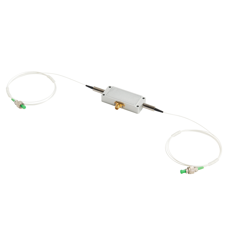
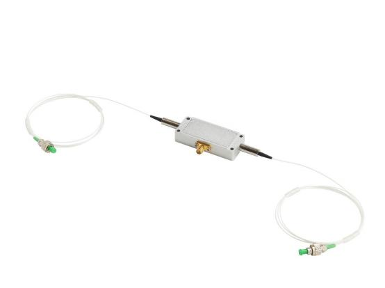
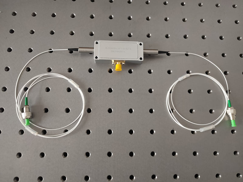
1550nm Fibre-Coupled Acousto-Optic Modulator 80Mhz
The 1550nm fiber coupled input acousto-optic modulator with 80Mhz frequency, 30ns rise time and low insertion loss can be used in systems such as fiber optic sensing.
Model:AOM-1550-80-A
Contact: Huang
Email: Hqy@ybphotonics.com
Huang
Email: Hqy@ybphotonics.com
Huang
Email: Hqy@ybphotonics.com
Introduction
1550nm fiber-coupled acousto-optic modulator for fiber optic sensing applications such as distributed fiber optic vibration sensing systems.
Download
 1550nm Fibre-Coupled Acousto-Optic Modulator.pdf download
Specifications
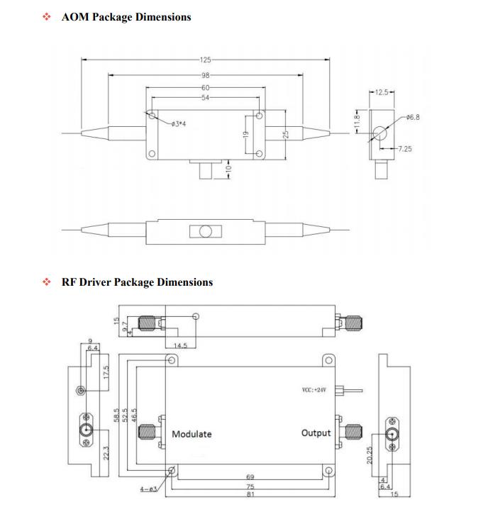
Parameter Unit Min Max Typical Comments Material TeO2 Wavelength nm 1520 1580 1550 Average optical power handling W 0.5 Peak (pulse) optical power handling W 0.5 Ultrasonic Velocity m/s 4200 Insertion Loss dB 3 2.5 Extinction Ratio (1st order on / off) dB 50 Return Loss (RF ON) dB 40 Rise-time / Fall-time: (10% - 90%) ns 30 Frequency MHz 80 Frequency Shift MHz +80 Radio Frequency Power W 2.5 VSWR 1.2:1 Input Impedance Ω 50 Device Interface SMA Fibre Type SMF-28e Fibre Length m 1 Fibre Termination FC/APC Working temperature C -20~60 Storage Temperature C -30~70
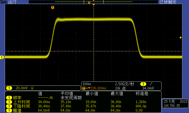
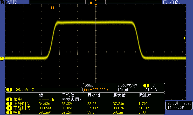
Acousto-optic modulator test data (oscilloscope screenshot)
Fiber-Coupled Acousto-Optical Modulator Device Instruction Manual
I. Methods of use
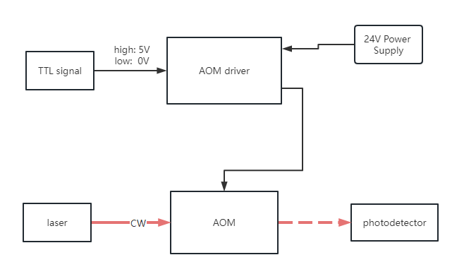
- drive power supply "+24V" port, please use the matching power supply cable, power supply cable one end according to the positive and negative level to connect the drive power supply "+24V" port, the other end of the power cord according to the positive and negative labeling correctly connected to the 24V power supply positive and negative (if the connection is reversed is likely to be directly burned out of the drive power supply)
- The output power of the drive power supply is adjustable. General factory before the RF output power has been and sound and light devices together with the supporting modulation. If there is no special demand, please do not adjust. If you need to change the RF power, please use a screwdriver to rotate the small hole knob in the "amplitude" end. Clockwise power decreases, counterclockwise power increases.
- drive power supply "power output" port, please use the matching SMA signal cable to connect: the other end of the signal cable SMA directly connected to the sound and light devices.
- The "Modulation" port is used to load the control signal, which is a standard TTL digital signal. Note: The power supply is on high, and 5V must be supplied to the "Modulation" port for RF power to be output.
- use of acousto-optic devices, the use of the laser source must be consistent with the purchase of the former v. Laser source, otherwise it will affect the acousto-optic device test when the insertion of the insertion loss becomes larger.
- When connecting the light source or photoelectric probe with the fiber optic interface of the acousto-optic device, please carefully confirm whether the fiber optic interface of the acousto-optic device is FC/PC or FC/APC. If the fiber optic interface of the acousto-optic device and the interface of the device to be connected do not coincide with each other, please use an adapter to ensure that the interface is consistent, or else it will affect the acousto-optic device to test the insertion of the insertion loss becomes larger.
II Notes
- Acousto-optic devices operate under high frequency conditions. To prevent human damage. When the "Power Output" terminal is not connected to the load (i.e., not connected to the acousto-optic device), do not load the 24V power supply, in order to prevent the RF source no-load caused by high-frequency oscillation damage to the components. Especially after the test is completed, always remember to turn off the 24V power supply in time to avoid the drive power supply no load.
- drive power supply in the power before, please be sure to drive the power supply placed or fixed to a good heat dissipation effect of the metal plate, to avoid because of the drive of the poor heat dissipation effect caused by the power supply internal components damage.
- Pay attention to protect the optical fiber to avoid damage or breakage.
- Cap the fiber optic interface after use, to avoid wear or pollution of the interface end face:5Products should be gently held and placed to avoid impact.
Related content
1550nm fiber-coupled acousto-optic modulator for fiber optic sensing applications such as distributed fiber optic vibration sensing systems.
Download
![]() 1550nm Fibre-Coupled Acousto-Optic Modulator.pdf download
1550nm Fibre-Coupled Acousto-Optic Modulator.pdf download
Specifications
| Parameter | Unit | Min | Max | Typical | Comments |
|---|---|---|---|---|---|
| Material | TeO2 | ||||
| Wavelength | nm | 1520 | 1580 | 1550 | |
| Average optical power handling | W | 0.5 | |||
| Peak (pulse) optical power handling | W | 0.5 | |||
| Ultrasonic Velocity | m/s | 4200 | |||
| Insertion Loss | dB | 3 | 2.5 | ||
| Extinction Ratio (1st order on / off) | dB | 50 | |||
| Return Loss (RF ON) | dB | 40 | |||
| Rise-time / Fall-time: (10% - 90%) | ns | 30 | |||
| Frequency | MHz | 80 | |||
| Frequency Shift | MHz | +80 | |||
| Radio Frequency Power | W | 2.5 | |||
| VSWR | 1.2:1 | ||||
| Input Impedance | Ω | 50 | |||
| Device Interface | SMA | ||||
| Fibre Type | SMF-28e | ||||
| Fibre Length | m | 1 | |||
| Fibre Termination | FC/APC | ||||
| Working temperature | C | -20~60 | |||
| Storage Temperature | C | -30~70 |
Acousto-optic modulator test data (oscilloscope screenshot)
Fiber-Coupled Acousto-Optical Modulator Device Instruction Manual
I. Methods of use
- drive power supply "+24V" port, please use the matching power supply cable, power supply cable one end according to the positive and negative level to connect the drive power supply "+24V" port, the other end of the power cord according to the positive and negative labeling correctly connected to the 24V power supply positive and negative (if the connection is reversed is likely to be directly burned out of the drive power supply)
- The output power of the drive power supply is adjustable. General factory before the RF output power has been and sound and light devices together with the supporting modulation. If there is no special demand, please do not adjust. If you need to change the RF power, please use a screwdriver to rotate the small hole knob in the "amplitude" end. Clockwise power decreases, counterclockwise power increases.
- drive power supply "power output" port, please use the matching SMA signal cable to connect: the other end of the signal cable SMA directly connected to the sound and light devices.
- The "Modulation" port is used to load the control signal, which is a standard TTL digital signal. Note: The power supply is on high, and 5V must be supplied to the "Modulation" port for RF power to be output.
- use of acousto-optic devices, the use of the laser source must be consistent with the purchase of the former v. Laser source, otherwise it will affect the acousto-optic device test when the insertion of the insertion loss becomes larger.
- When connecting the light source or photoelectric probe with the fiber optic interface of the acousto-optic device, please carefully confirm whether the fiber optic interface of the acousto-optic device is FC/PC or FC/APC. If the fiber optic interface of the acousto-optic device and the interface of the device to be connected do not coincide with each other, please use an adapter to ensure that the interface is consistent, or else it will affect the acousto-optic device to test the insertion of the insertion loss becomes larger.
II Notes
- Acousto-optic devices operate under high frequency conditions. To prevent human damage. When the "Power Output" terminal is not connected to the load (i.e., not connected to the acousto-optic device), do not load the 24V power supply, in order to prevent the RF source no-load caused by high-frequency oscillation damage to the components. Especially after the test is completed, always remember to turn off the 24V power supply in time to avoid the drive power supply no load.
- drive power supply in the power before, please be sure to drive the power supply placed or fixed to a good heat dissipation effect of the metal plate, to avoid because of the drive of the poor heat dissipation effect caused by the power supply internal components damage.
- Pay attention to protect the optical fiber to avoid damage or breakage.
- Cap the fiber optic interface after use, to avoid wear or pollution of the interface end face:5Products should be gently held and placed to avoid impact.
Related content
Product Inquiry
Leading manufacturer of photodetector modules and fiber optic sensing system modules