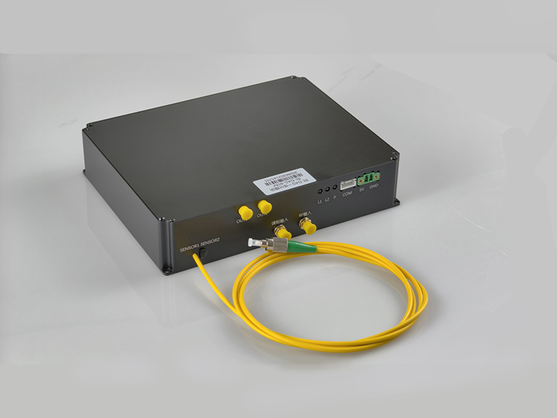
DAS Integration Module Supporting Customized Pulsed RF Input
A DAS integration module supporting customised pulsed RF inputs, capable of accepting 80/200 MHz pulse signals and also receiving chirp-modulated pulse signals.
 Huang
Email: Hqy@ybphotonics.com
Huang
Email: Hqy@ybphotonics.com
Summarize
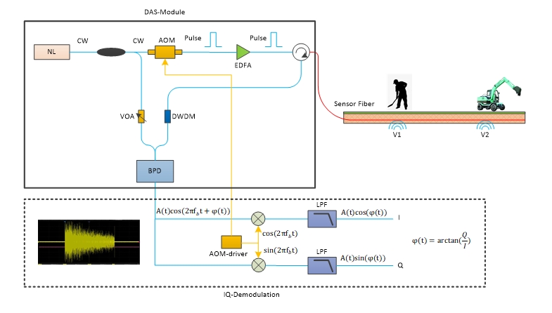
This DAS module serves as the optical path for distributed acoustic sensing (DAS); it supports user-defined RF pulse inputs. Users can select either an 80 MHz or 200 MHz intermediate frequency signal and input the corresponding signal via an AWG, or it can receive user-generated chirped pulse signals.
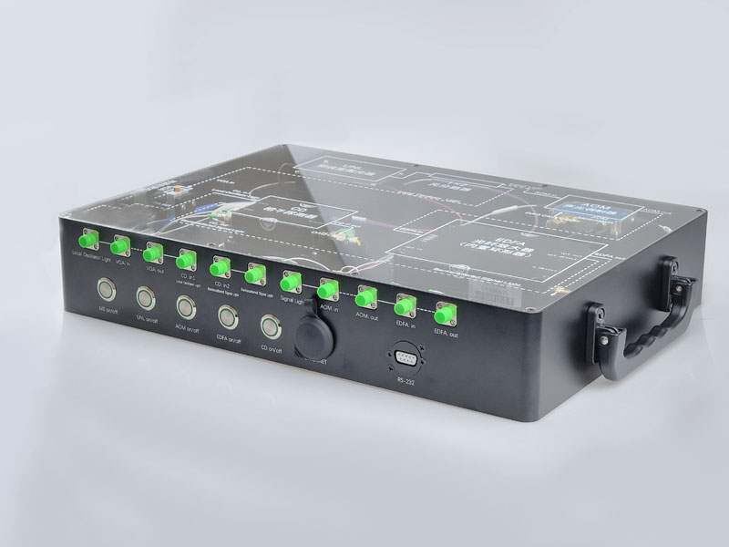
Internal Optical Path Diagram of the Module
Core Parameters
| Parameter | Value | Remarks |
|---|---|---|
| Number of Channels | 1 | 2 channels optional |
| Supported Distance per Channel | 40 km | — |
| Laser Linewidth | <3 kHz | 1 kHz optional |
| Intermediate Frequency (IF) | 80 MHz | 200 MHz optional |
| RF Input | Supported | Users can customise RF pulse signals. |
| Spatial Resolution | 2–10 m | Adjustable pulse width: 20 ns–100 ns |
| Module Debug Interface | TTL Serial Port | — |
| Module Debug Protocol | Modbus‑RTU | — |
| Operating Temperature | -20 °C to 60 °C | — |
| Storage Temperature | -40 °C to 80 °C | — |
Differences between this module and other standard DAS modules
This module supports full-range RF signal input. For example, if you select a DAS module designed for a 200 MHz intermediate frequency signal, you can use an AWG to directly output a 200 MHz signal. Alternatively, you can provide your own chirped pulse signals to achieve higher-performance DAS.
Interface Definition
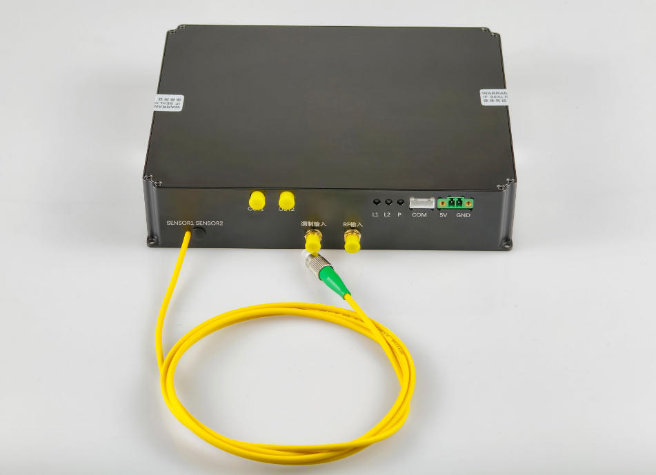
| Interface Type | Silkscreen | Description |
|---|---|---|
| Green Plug-in Terminal | 12V | DC power supply +12V power input |
| Green Plug-in Terminal | GND | DC power supply GND |
| White Plug-in Terminal | COM | Serial port, TTL level, used for parameter adjustment by communicating with a computer |
| SMA | Modulation Input | AOM modulation signal input |
| SMA | RF Input | Dedicated for chirp models |
| Optical Fiber Interface | Sensor1 | Connect to sensing fiber 1, default FC/APC connector, used for single-channel products |
| Optical Fiber Interface | Sensor2 | Connect to sensing fiber 2, default FC/APC connector |
| SMA | OUT1 | Module channel 1 output voltage signal, used for single-channel products |
| SMA | OUT2 | Module channel 2 output voltage signal |
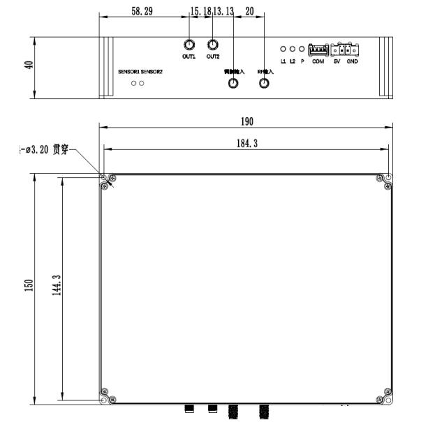
Mechanical Dimension Drawing
What kind of capture card is needed?
Since this DAS module requires the output of 80/200 MHz RF signals, the data acquisition card must include an AWG function. To meet this requirement, we have specifically developed a 1 Gbps high-speed data acquisition card that also integrates an AWG function.

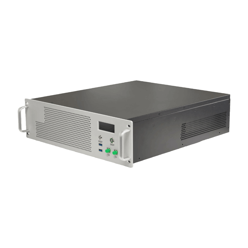
GY-DAQA-2510, View Detail
The pulse modulation of the DAS module is generated by the RF pulse modulator on the acquisition card, and the TTL trigger output signal from the acquisition card is used to enable modulation of the module.
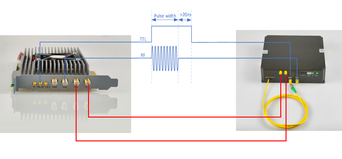
Schematic Diagram of the Connection Between the GY-DAQA-2510 and the DAS Module
- Connect the AWG1 pin on the data acquisition card to the RF input of the DAS module.
- Connect the trigger output of the data acquisition card to the modulation input of the DAS module.
- Connect CH1 on the data acquisition card to CH1 on the DAS module.
- Connect CH2 on the data acquisition card to CH2 on the DAS module (if the DAS module has only one sensor fiber, this connection is optional).
Ordering Information
| Model | Type | Channels | Distance | Intermediate Frequency | Laser linewidth | Features |
|---|---|---|---|---|---|---|
| GY-DAS-RF-1-1-40-80 | RF Signal Input | 1 | ≤40km | 80M | <1kHz | Good signal quality |
| GY-DAS-RF-2-1-40-80 | RF Signal Input | 2 | ≤40km | 80M | <1kHz | Good signal quality |
| GY-DAS-RF-1-3-40-80 | RF Signal Input | 1 | ≤40km | 80M | <3kHz | Good signal quality |
| GY-DAS-RF-2-3-40-80 | RF Signal Input | 2 | ≤40km | 80M | <3kHz | Good signal quality |
| GY-DAS-RF-1-1-40-200 | RF Signal Input | 1 | ≤40km | 200M | <1kHz | Good signal quality |
| GY-DAS-RF-2-1-40-200 | RF Signal Input | 2 | ≤40km | 200M | <1kHz | Good signal quality |
| GY-DAS-RF-1-3-40-200 | RF Signal Input | 1 | ≤40km | 200M | <3kHz | Good signal quality |
| GY-DAS-RF-2-3-40-200 | RF Signal Input | 2 | ≤40km | 200M | <3kHz | Good signal quality |
Testing the background noise at different pulse frequencies
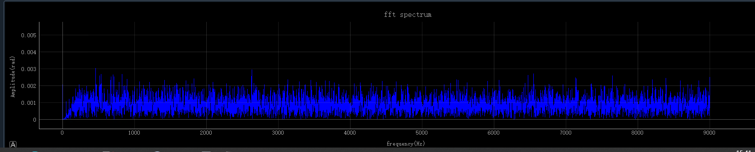
When the pulse frequency is set to 18kHz, the background noise signal is clean, with no abnormal frequencies.
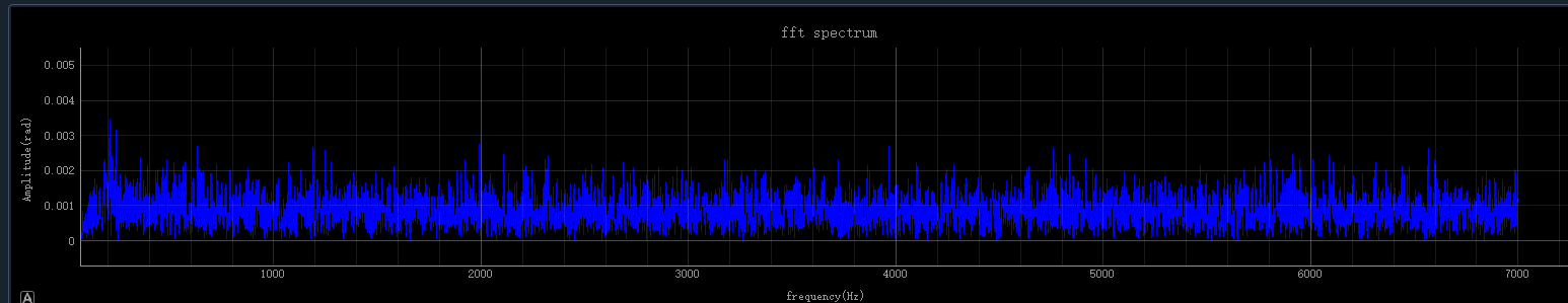
When the pulse frequency is set to 14kHz, the background noise signal is clean, with no abnormal frequencies.
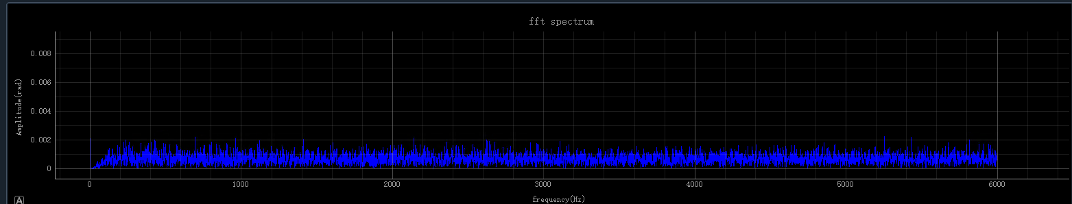
When the pulse frequency is set to 12kHz, the background noise signal is clean, with no abnormal frequencies.
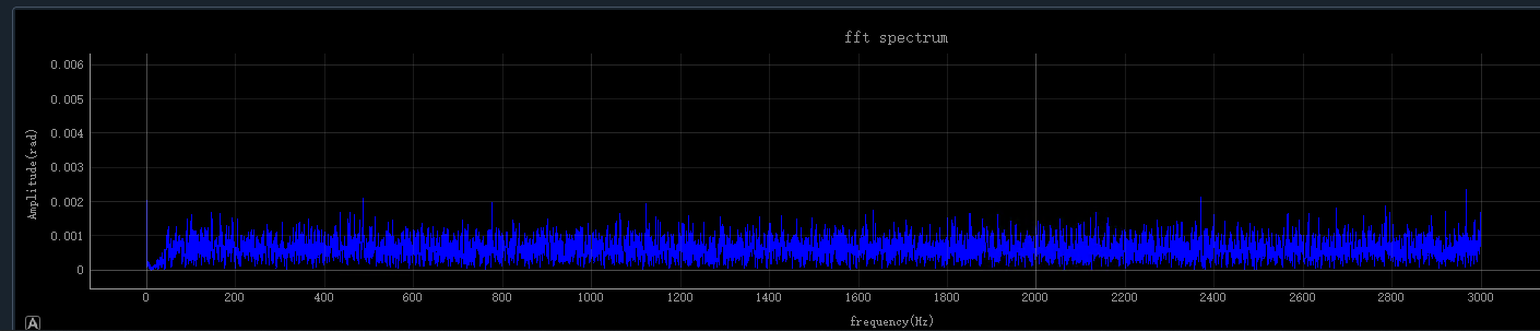
When the pulse frequency is set to 6kHz, the background noise signal is clean, with no abnormal frequencies.
FAQ
-
Q: What is the lead time for your fiber optic sensing related module products?
A: Basically, we have more than 90% of modules in stock, only a few models need 2 weeks lead time. -
Q: Do you support the sale of those countries, and is the shipping included?
A: Our service is available worldwide, regardless of country or region. Shipping is included. -
Q: Who are your typical customers?
A: More than 100 top universities and research institutes in China have chosen us and given us high evaluations, such as: Chinese Academy of Sciences, CEC, Tsinghua University, Peking University and other clients.