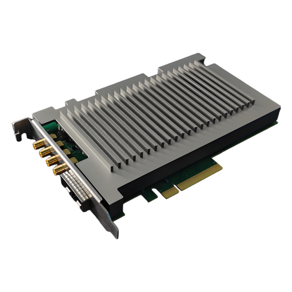
DVS-ETH-100-1 High-Speed Data Acquisition Card for Fiber Optic Sensing
The acquisition card is customized for distributed fiber optic vibration DVS system, with dual-channel synchronous sampling, 100M sampling rate, 12-bit, with trigger output function, and built-in averaging and differential algorithms.
 Huang
Email: Hqy@ybphotonics.com
Huang
Email: Hqy@ybphotonics.com
 Download>>
Introduction
The DVS-ETH-100-1 is a 12-bit dual-channel high-speed data acquisition card exclusively engineered for DVS distributed fiber optic vibration sensing systems. With 100MSps synchronous sampling, Gigabit Ethernet connectivity, and built-in averaging/differential demodulation algorithms, it supports real-time data collection for up to 100+ km fiber optic links. Featuring plug-and-play integration (no complex drivers) and industrial-grade stability, it is the ideal data acquisition solution for fiber optic vibration, and structural health monitoring applications.
As a high-speed data acquisition card for DVS, DVS-ETH-100M-1 adopts Gigabit Ethernet interface to communicate with the host computer, avoiding complicated driver installation and supporting cross-platform use, which is convenient for users to integrate and use.
The acquisition card adopts dual-channel 12bit high-speed ADC, the highest sampling rate support 100MSps, the highest support more than 100km DVS data acquisition, built-in average, differential demodulation algorithms, can directly upload differential demodulation data, the user can be used directly as the vibration data, you can also upload the original sampling data, for the user to demodulate their own.
API Documentation And Software Downloads
Specification
■ 12bits dual-channel synchronized real-time sampling
■ 100MSps sampling rate
■ DC coupling, 50Ω input impedance
■ 2Vpp input voltage range, 0-50MHz analog bandwidth
■ ±1V bias programmable to fully utilize ADC range
■ Up to 88dBc SFDR
■ Trigger Output Pulse
■ Gigabit Ethernet high-speed transmission interface
■ Built-in fiber optic sensing demodulation algorithm
Power Supply and Consumption
■ Power supply: 12V, 0.6A
■ Power consumption: 5W (Max)
Temperature range
■ Working Temperature: -20~60°C
■ Storage temperature:-40~85℃
Mechanical dimensions
■ 100mm(L)x70mm(W)x20mm(D)
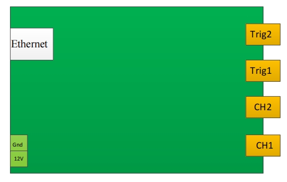
Interface definition
- Ethernet: Gigabit Ethernet port for data transmission and parameter setting
- Power supply: 12 V supply
- Ch1: Acquisition channel 1
- Ch2: Acquisition channel 2
- Trigger1: external trigger, 3.3V input
- Trigger2: internal acquisition trigger output, 3.3V/5V selectable
Interface Definitions
IP address
The acquisition card uses UDP transmission protocol to communicate with the host computer. Before communication, you need to set the host computer's IP address and port according to the following parameters:
FPGA IP:192.168.137.2 port:6789
PC IP:192.168.137.3 data port:6788,command port:6787
Data and command sampling are received separately on different ports for easy processing by the host computer.
UDP message format
8.1PC to FPGA (send)
Header(6 bytes) Functionality(2 bytes) Command(2 bytes) Data length(4 bytes) Standby(2 bytes) Digital 0xA55AAA5555AA 0x0001:issue orders0x0002:read data Send commands according to the instructions in section 4 Length of the data to be sent reservation pending data
Each time the PC sends a command to the FPGA, the FPGA will return the query result of the corresponding command, if it does not return the query result command, it is considered that the sending command fails, and the program can be written to do a timeout to receive it, and if the sending command fails to be retransmitted once.
Example 1 (Setting the number of samples to 1024):
Header(6 bytes) Functionality(2 bytes) Command(2 bytes) Data length(4 bytes) Standby(2 bytes) Data(8 bytes) 0xA55AAA5555AA 0x0001 0x0002 0x00000008 0x0000 0x0000000000000400(1024)
Example 2 (Querying the number of sampling points):
Header(6 bytes) Functionality(2 bytes) Command(2 bytes) Data length(4 bytes) Standby(2 bytes) Data(8 bytes) 0xA55AAA5555AA 0x0002 0x0002 0x00000008 0x0000 0x0000000000000000
8.2FPGA to PC (receive)
8.2.1Receive command query results (receive port: 6003)
Header Functionality Reservations Data length Data (6 bytes) (2 bytes) (2 bytes) (2 bytes) Command Result (2 bytes) (2 bytes) 0x5AA555AAAA55 0x0002 0x0001 Data length Query command Inquiry results
Example (Querying Sampling Points Results):
Header Functionality Reservations Data length Data (6 bytes) (2 bytes) (2 bytes) (2 bytes) Command Result (2 bytes) (2 bytes) 0x5AA555AAAA55 0x0002 0x0001 0x0004 0x0002 0x1000
8.2.2Receiving Sampling Data (Receive Port: 6001)
Header(6 bytes) Functionality(2 bytes) Reservations(2 bytes) Data symbol(2 bytes) Package number(2 bytes) Packet length(2 bytes) Data 0x5AA555AAAA55 0x0003 0x0000 0x0011:Normal data 0x1100:End of data Current UDP message sequence number, which can be used to determine packet loss (sequence +1) Packet length(Maximum 1024+16) Sampling data(uint16)
Data Description:The sampling data is stored in unsigned short int format, and one sampling point occupies 2Bytes. A UDP message can upload 1024 Bytes of sampling data at most, i.e., 512 sampling points.When the number of sampling points is greater than 512 sampling points, a group of pulse-triggered sampling data will be divided into multiple UDP messages to be uploaded, and the message flags are differentiated by the data flags. When the 0x1100 flag is detected, it indicates that a group of complete sampling data sampling is completed, and the packet signal is used to determine whether a packet loss is generated, and the sequence of packet signals is increased by 1.
For example, if the number of sampling points is 4000, then one trigger sampling will be divided into 4000/512=7.8125≈8 UDP messages to upload, the first 7 message data length is 1024Bytes (512 sampling points), data flag bit 0x0011, packet sequence number is 0-6, the last message data length is 832Bytes (416 sampling points), data flag bit 0x1100, packet sequence number is 7, subsequent trigger sampling as above.
When dual-channel acquisition, the total number of points of each triggered sample is 2 times of the sample length, and the data is stored alternately according to ch1|ch2|ch1|ch2.......
Command Description
9.1. Start/End command(0x0001)
Definition: start or stop sampling, after starting sampling, sampling data will be uploaded continuously, stopping sampling will end uploading data
Header(6 bytes) Functionality(2 bytes) Command(2bytes) Data length(4bytes) Standby(2bytes) Digital(8bytes) 0xA55AAA5555AA 0x0001 0x0001 0x00000008 0x0000 0x0000000000000001:Start collecting0x0000000000000000:Stop collecting
9.2. Sampling length(0x0002)
Definition: the number of data points sampled by one pulse trigger, must be a multiple of 4, default value: 4096, maximum value 32000
Header(6 bytes) Functionality(2 bytes) Command(2 bytes) Data length(4 bytes) Standby(2 bytes) Digital(8 bytes) 0xA55AAA5555AA 0x0001 0x0002 0x00000008 0x0000 0x0000000000001000
9.3. Sampling delay points(0x0010)
Definition: number of delayed sampling points after the rising edge of trigger pulse, default value: 100
Header(6 bytes) Functionality(2 bytes) Command(2 bytes) Data length(4 bytes) Standby(2 bytes) Digital(8 bytes) 0xA55AAA5555AA 0x0001 0x0010 0x00000008 0x0000 0x0000000000000064
9.4. Pulse frequency(0x0004)
Definition: Trigger output pulse frequency issued by the sampling card, default value: 2000
Header(6 bytes) Functionality(2 bytes) Command(2 bytes) Data length(4 bytes) Standby(2 bytes) Digital(8 bytes) 0xA55AAA5555AA 0x0001 0x0004 0x00000008 0x0000 0x00000000000007D0
9.5. Pulse width(0x0011)
Definition: Trigger output pulse width (ns) issued by the sampling card, default value: 100
Header(6 bytes) Functionality(2 bytes) Command(2 bytes) Data length(4 bytes) Standby(2 bytes) Digital(8 bytes) 0xA55AAA5555AA 0x0001 0x0011 0x00000008 0x0000 0x0000000000000064
9.6. Setting the average(0x0008)
Definition: the sampling card averages the data collected for each trigger, default value: 0, default off
Header(6 bytes) Functionality(2 bytes) Command(2 bytes) Data length(4 bytes) Standby(2 bytes) Digital(8 bytes) 0xA55AAA5555AA 0x0001 0x0008 0x00000008 0x0000 0x000000000000000:cloture0x000000000000001:open
The acquisition card averages the data obtained from m pulse-triggered samples and compresses the data to one pulse-triggered data.
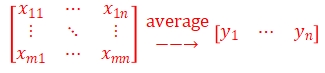
Where "m" is the number of trigger pulses collected, "n" is the number of points collected per trigger, and the average number of times "m" can be set for the averaged pulse-triggered data for final upload.
9.7. Average number of times(0x0020)
Definition: the average number of times to trigger the acquisition of data, default value: 64, can be set: 8, 16, 32, 64, 128
Header(6 bytes) Functionality(2 bytes) Command(2 bytes) Data length(4 bytes) Standby(2 bytes) Digital(8 bytes) 0xA55AAA5555AA 0x0001 0x0020 0x00000008 0x0000 0x0000000000000040
9.8. Setting up differential(0x0021)
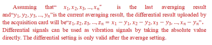
Definition: the sampling card differentiates the data for each average, default value: 0
Header(6 bytes) Functionality(2 bytes) Command(2 bytes) Data length(4 bytes) Standby(2 bytes) Digital(8 bytes) 0xA55AAA5555AA 0x0001 0x0021 0x00000008 0x0000 0x000000000000000:cloture0x000000000000001:open
9.9. Sample Rate Setting(0x0022)
Definition: Set the sampling rate of the capture card, default value: 5, can be set: 1, 2, 3, 4, 5, 6.
The parameter value corresponds to the sampling rate:
1:10MSps, corresponding to a sampling resolution of 10m;
2:20MSps, corresponding to a sampling resolution of 5m;
3:40MSps, corresponding to a sampling resolution of 2.5m;
4:50MSps, corresponding to a sampling resolution of 2m;
5:100MSps, corresponding to a sampling resolution of 1m;
Header(6 bytes) Functionality(2 bytes) Command(2 bytes) Data length(4 bytes) Standby(2 bytes) Digital(8 bytes) 0xA55AAA5555AA 0x0001 0x0022 0x00000008 0x0000 0x0000000000000005
9.10. Bias Voltage Setting(0x0023)
Definition: Set ADC sampling bias voltage, default value: 0, can be set: 0-4096mv, 1000mv corresponds to 0 bias, 0mv corresponds to +1v bias, 2000mv corresponds to -1v bias.
Header(6 bytes) Functionality(2 bytes) Command(2 bytes) Data length(4 bytes) Standby(2 bytes) Digital(8 bytes) 0xA55AAA5555AA 0x0001 0x0023 0x00000008 0x0000 0x0000000000000000
Notes:
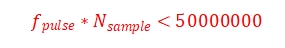
10.1、The sampling rate, pulse re-frequency and the number of sampling points should satisfy the following relationship:
Where  is the pulse re-frequency,
 is the sampling rate,and
  is the number of sampling points.
For example, the fiber length of 40km, sampling rate of 50MPS, corresponding to the sampling resolution of 2m, then the number of sampling points should be 40km/2m = 20000, in order to cover the entire cable, so the pulse frequency should meet:
In addition, the number of sampling points and reclocking should also be satisfied in order to meet the Gigabit Ethernet transmission bandwidth:
Usually used as a DVS acquisition, it is recommended that the pulse re-frequency should not exceed 2000, the number of sampling points multiplied by the sampling resolution is slightly higher than the length of the fiber optic cable.
10.2、At present, the capture card only opens channel one Functionality, channel two is not available for the time being.
10.3、Capture card calling process:
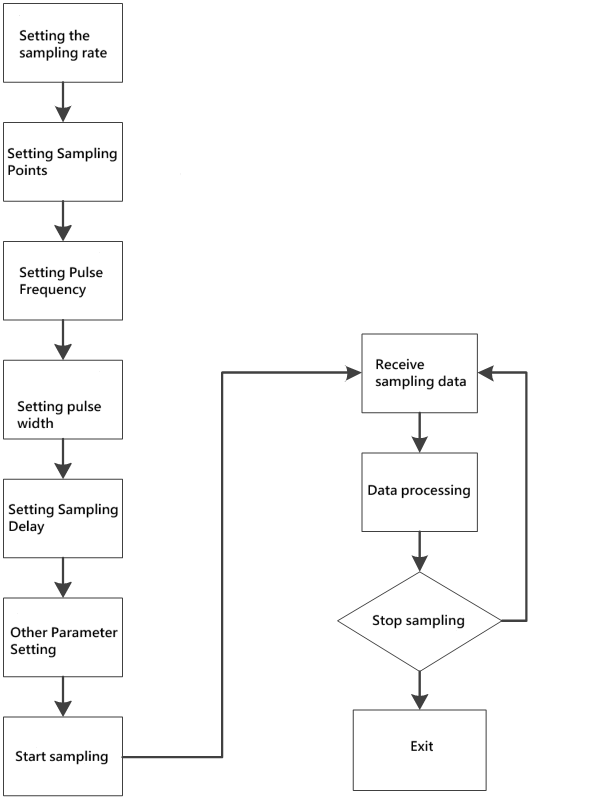
Command invocation flow
It is best to set all the parameters once before the sampling starts to ensure that the parameters of the acquisition card are consistent with the expectations, and after the start of the acquisition, you can adjust the parameters and query the parameter values of the acquisition card in real time halfway through the process.
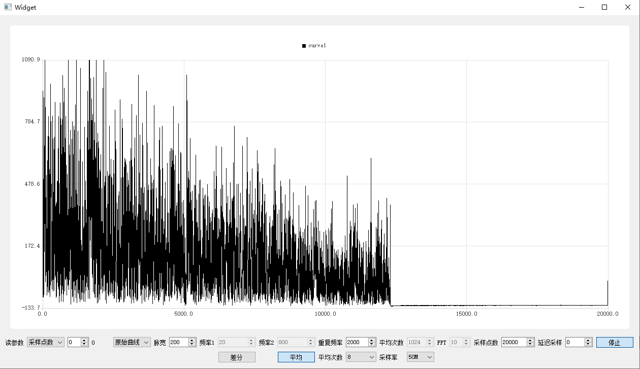
Test results
Original curve
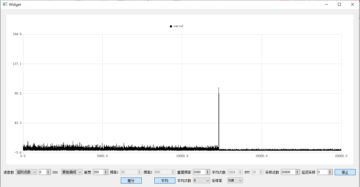
Vibration curve
The DVS-ETH-100-1 is a 12-bit dual-channel high-speed data acquisition card exclusively engineered for DVS distributed fiber optic vibration sensing systems. With 100MSps synchronous sampling, Gigabit Ethernet connectivity, and built-in averaging/differential demodulation algorithms, it supports real-time data collection for up to 100+ km fiber optic links. Featuring plug-and-play integration (no complex drivers) and industrial-grade stability, it is the ideal data acquisition solution for fiber optic vibration, and structural health monitoring applications.
As a high-speed data acquisition card for DVS, DVS-ETH-100M-1 adopts Gigabit Ethernet interface to communicate with the host computer, avoiding complicated driver installation and supporting cross-platform use, which is convenient for users to integrate and use.
The acquisition card adopts dual-channel 12bit high-speed ADC, the highest sampling rate support 100MSps, the highest support more than 100km DVS data acquisition, built-in average, differential demodulation algorithms, can directly upload differential demodulation data, the user can be used directly as the vibration data, you can also upload the original sampling data, for the user to demodulate their own.
API Documentation And Software Downloads
Specification
■ 12bits dual-channel synchronized real-time sampling
■ 100MSps sampling rate
■ DC coupling, 50Ω input impedance
■ 2Vpp input voltage range, 0-50MHz analog bandwidth
■ ±1V bias programmable to fully utilize ADC range
■ Up to 88dBc SFDR
■ Trigger Output Pulse
■ Gigabit Ethernet high-speed transmission interface
■ Built-in fiber optic sensing demodulation algorithm
Power Supply and Consumption
■ Power supply: 12V, 0.6A
■ Power consumption: 5W (Max)
Temperature range
■ Working Temperature: -20~60°C
■ Storage temperature:-40~85℃
Mechanical dimensions
■ 100mm(L)x70mm(W)x20mm(D)
Interface definition
- Ethernet: Gigabit Ethernet port for data transmission and parameter setting
- Power supply: 12 V supply
- Ch1: Acquisition channel 1
- Ch2: Acquisition channel 2
- Trigger1: external trigger, 3.3V input
- Trigger2: internal acquisition trigger output, 3.3V/5V selectable
Interface Definitions
IP address
The acquisition card uses UDP transmission protocol to communicate with the host computer. Before communication, you need to set the host computer's IP address and port according to the following parameters:
FPGA IP:192.168.137.2 port:6789
PC IP:192.168.137.3 data port:6788,command port:6787
Data and command sampling are received separately on different ports for easy processing by the host computer.
UDP message format
8.1PC to FPGA (send)
| Header(6 bytes) | Functionality(2 bytes) | Command(2 bytes) | Data length(4 bytes) | Standby(2 bytes) | Digital |
|---|---|---|---|---|---|
| 0xA55AAA5555AA | 0x0001:issue orders0x0002:read data | Send commands according to the instructions in section 4 | Length of the data to be sent | reservation | pending data |
Each time the PC sends a command to the FPGA, the FPGA will return the query result of the corresponding command, if it does not return the query result command, it is considered that the sending command fails, and the program can be written to do a timeout to receive it, and if the sending command fails to be retransmitted once.
Example 1 (Setting the number of samples to 1024):
| Header(6 bytes) | Functionality(2 bytes) | Command(2 bytes) | Data length(4 bytes) | Standby(2 bytes) | Data(8 bytes) |
|---|---|---|---|---|---|
| 0xA55AAA5555AA | 0x0001 | 0x0002 | 0x00000008 | 0x0000 | 0x0000000000000400(1024) |
Example 2 (Querying the number of sampling points):
| Header(6 bytes) | Functionality(2 bytes) | Command(2 bytes) | Data length(4 bytes) | Standby(2 bytes) | Data(8 bytes) |
|---|---|---|---|---|---|
| 0xA55AAA5555AA | 0x0002 | 0x0002 | 0x00000008 | 0x0000 | 0x0000000000000000 |
8.2FPGA to PC (receive)
8.2.1Receive command query results (receive port: 6003)
| Header | Functionality | Reservations | Data length | Data | |
| (6 bytes) | (2 bytes) | (2 bytes) | (2 bytes) | ||
| Command | Result | ||||
| (2 bytes) | (2 bytes) | ||||
| 0x5AA555AAAA55 | 0x0002 | 0x0001 | Data length | Query command | Inquiry results |
Example (Querying Sampling Points Results):
| Header | Functionality | Reservations | Data length | Data | |
| (6 bytes) | (2 bytes) | (2 bytes) | (2 bytes) | ||
| Command | Result | ||||
| (2 bytes) | (2 bytes) | ||||
| 0x5AA555AAAA55 | 0x0002 | 0x0001 | 0x0004 | 0x0002 | 0x1000 |
8.2.2Receiving Sampling Data (Receive Port: 6001)
| Header(6 bytes) | Functionality(2 bytes) | Reservations(2 bytes) | Data symbol(2 bytes) | Package number(2 bytes) | Packet length(2 bytes) | Data |
|---|---|---|---|---|---|---|
| 0x5AA555AAAA55 | 0x0003 | 0x0000 | 0x0011:Normal data 0x1100:End of data | Current UDP message sequence number, which can be used to determine packet loss (sequence +1) | Packet length(Maximum 1024+16) | Sampling data(uint16) |
Data Description:The sampling data is stored in unsigned short int format, and one sampling point occupies 2Bytes. A UDP message can upload 1024 Bytes of sampling data at most, i.e., 512 sampling points.When the number of sampling points is greater than 512 sampling points, a group of pulse-triggered sampling data will be divided into multiple UDP messages to be uploaded, and the message flags are differentiated by the data flags. When the 0x1100 flag is detected, it indicates that a group of complete sampling data sampling is completed, and the packet signal is used to determine whether a packet loss is generated, and the sequence of packet signals is increased by 1.
For example, if the number of sampling points is 4000, then one trigger sampling will be divided into 4000/512=7.8125≈8 UDP messages to upload, the first 7 message data length is 1024Bytes (512 sampling points), data flag bit 0x0011, packet sequence number is 0-6, the last message data length is 832Bytes (416 sampling points), data flag bit 0x1100, packet sequence number is 7, subsequent trigger sampling as above.
When dual-channel acquisition, the total number of points of each triggered sample is 2 times of the sample length, and the data is stored alternately according to ch1|ch2|ch1|ch2.......
Command Description
9.1. Start/End command(0x0001)
Definition: start or stop sampling, after starting sampling, sampling data will be uploaded continuously, stopping sampling will end uploading data
| Header(6 bytes) | Functionality(2 bytes) | Command(2bytes) | Data length(4bytes) | Standby(2bytes) | Digital(8bytes) |
|---|---|---|---|---|---|
| 0xA55AAA5555AA | 0x0001 | 0x0001 | 0x00000008 | 0x0000 | 0x0000000000000001:Start collecting0x0000000000000000:Stop collecting |
9.2. Sampling length(0x0002)
Definition: the number of data points sampled by one pulse trigger, must be a multiple of 4, default value: 4096, maximum value 32000
| Header(6 bytes) | Functionality(2 bytes) | Command(2 bytes) | Data length(4 bytes) | Standby(2 bytes) | Digital(8 bytes) |
|---|---|---|---|---|---|
| 0xA55AAA5555AA | 0x0001 | 0x0002 | 0x00000008 | 0x0000 | 0x0000000000001000 |
9.3. Sampling delay points(0x0010)
Definition: number of delayed sampling points after the rising edge of trigger pulse, default value: 100
| Header(6 bytes) | Functionality(2 bytes) | Command(2 bytes) | Data length(4 bytes) | Standby(2 bytes) | Digital(8 bytes) |
|---|---|---|---|---|---|
| 0xA55AAA5555AA | 0x0001 | 0x0010 | 0x00000008 | 0x0000 | 0x0000000000000064 |
9.4. Pulse frequency(0x0004)
Definition: Trigger output pulse frequency issued by the sampling card, default value: 2000
| Header(6 bytes) | Functionality(2 bytes) | Command(2 bytes) | Data length(4 bytes) | Standby(2 bytes) | Digital(8 bytes) |
|---|---|---|---|---|---|
| 0xA55AAA5555AA | 0x0001 | 0x0004 | 0x00000008 | 0x0000 | 0x00000000000007D0 |
9.5. Pulse width(0x0011)
Definition: Trigger output pulse width (ns) issued by the sampling card, default value: 100
| Header(6 bytes) | Functionality(2 bytes) | Command(2 bytes) | Data length(4 bytes) | Standby(2 bytes) | Digital(8 bytes) |
|---|---|---|---|---|---|
| 0xA55AAA5555AA | 0x0001 | 0x0011 | 0x00000008 | 0x0000 | 0x0000000000000064 |
9.6. Setting the average(0x0008)
Definition: the sampling card averages the data collected for each trigger, default value: 0, default off
| Header(6 bytes) | Functionality(2 bytes) | Command(2 bytes) | Data length(4 bytes) | Standby(2 bytes) | Digital(8 bytes) |
|---|---|---|---|---|---|
| 0xA55AAA5555AA | 0x0001 | 0x0008 | 0x00000008 | 0x0000 | 0x000000000000000:cloture0x000000000000001:open |
The acquisition card averages the data obtained from m pulse-triggered samples and compresses the data to one pulse-triggered data.
Where "m" is the number of trigger pulses collected, "n" is the number of points collected per trigger, and the average number of times "m" can be set for the averaged pulse-triggered data for final upload.
9.7. Average number of times(0x0020)
Definition: the average number of times to trigger the acquisition of data, default value: 64, can be set: 8, 16, 32, 64, 128
| Header(6 bytes) | Functionality(2 bytes) | Command(2 bytes) | Data length(4 bytes) | Standby(2 bytes) | Digital(8 bytes) |
|---|---|---|---|---|---|
| 0xA55AAA5555AA | 0x0001 | 0x0020 | 0x00000008 | 0x0000 | 0x0000000000000040 |
9.8. Setting up differential(0x0021)
Definition: the sampling card differentiates the data for each average, default value: 0
| Header(6 bytes) | Functionality(2 bytes) | Command(2 bytes) | Data length(4 bytes) | Standby(2 bytes) | Digital(8 bytes) |
|---|---|---|---|---|---|
| 0xA55AAA5555AA | 0x0001 | 0x0021 | 0x00000008 | 0x0000 | 0x000000000000000:cloture0x000000000000001:open |
9.9. Sample Rate Setting(0x0022)
Definition: Set the sampling rate of the capture card, default value: 5, can be set: 1, 2, 3, 4, 5, 6.
The parameter value corresponds to the sampling rate:
1:10MSps, corresponding to a sampling resolution of 10m;
2:20MSps, corresponding to a sampling resolution of 5m;
3:40MSps, corresponding to a sampling resolution of 2.5m;
4:50MSps, corresponding to a sampling resolution of 2m;
5:100MSps, corresponding to a sampling resolution of 1m;
| Header(6 bytes) | Functionality(2 bytes) | Command(2 bytes) | Data length(4 bytes) | Standby(2 bytes) | Digital(8 bytes) |
|---|---|---|---|---|---|
| 0xA55AAA5555AA | 0x0001 | 0x0022 | 0x00000008 | 0x0000 | 0x0000000000000005 |
9.10. Bias Voltage Setting(0x0023)
Definition: Set ADC sampling bias voltage, default value: 0, can be set: 0-4096mv, 1000mv corresponds to 0 bias, 0mv corresponds to +1v bias, 2000mv corresponds to -1v bias.
| Header(6 bytes) | Functionality(2 bytes) | Command(2 bytes) | Data length(4 bytes) | Standby(2 bytes) | Digital(8 bytes) |
|---|---|---|---|---|---|
| 0xA55AAA5555AA | 0x0001 | 0x0023 | 0x00000008 | 0x0000 | 0x0000000000000000 |
Notes:
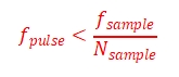
10.1、The sampling rate, pulse re-frequency and the number of sampling points should satisfy the following relationship:
Where ![]() is the pulse re-frequency,
is the pulse re-frequency,![]() is the sampling rate,and
is the sampling rate,and ![]() is the number of sampling points.
is the number of sampling points.
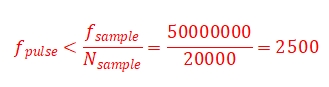
For example, the fiber length of 40km, sampling rate of 50MPS, corresponding to the sampling resolution of 2m, then the number of sampling points should be 40km/2m = 20000, in order to cover the entire cable, so the pulse frequency should meet:
In addition, the number of sampling points and reclocking should also be satisfied in order to meet the Gigabit Ethernet transmission bandwidth:
![]()
Usually used as a DVS acquisition, it is recommended that the pulse re-frequency should not exceed 2000, the number of sampling points multiplied by the sampling resolution is slightly higher than the length of the fiber optic cable.
10.2、At present, the capture card only opens channel one Functionality, channel two is not available for the time being.
10.3、Capture card calling process:
Command invocation flow
It is best to set all the parameters once before the sampling starts to ensure that the parameters of the acquisition card are consistent with the expectations, and after the start of the acquisition, you can adjust the parameters and query the parameter values of the acquisition card in real time halfway through the process.
Test results
Original curve
Vibration curve