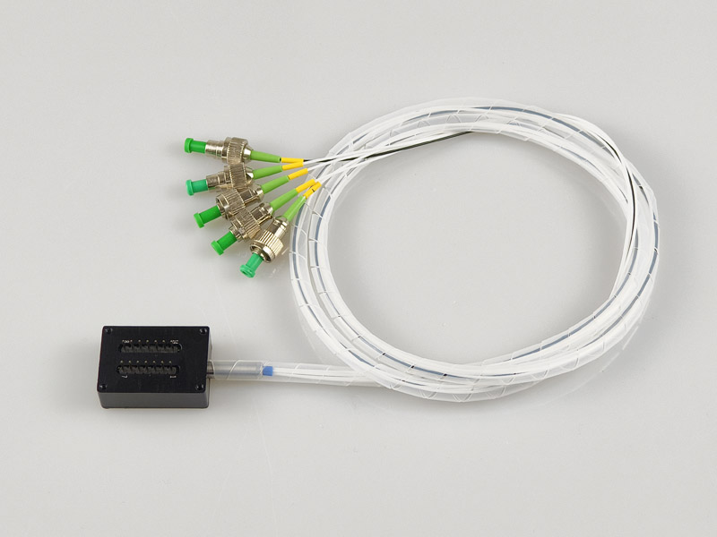
FSW-1×4 Multimode Optical Switch Module
FSW-1×4 multi-mode optical switching module is a device with the role of optical path switching
 Huang
Email: Hqy@ybphotonics.com
Huang
Email: Hqy@ybphotonics.com
Introduction
FSW-1×4 multi-mode optical switching module is a device with the role of optical path switching
Applications
FSW-1×4 multimode optical switching module is a functional device with the role of optical path switching, which is mainly used for the following purposes:
- Multiple optical monitoring in optical transmission system;
- LAN multi-light source/detector automatic switching, optical sensing multi-point dynamic monitoring system;
- Optical test system for optical fiber, optical device, network and field engineering optical cable testing;
- Optical device mounting.
Product Characteristics
- Low loss, high reliability;
- Simple parallel interface control;
- Modular design.
Product Performance
- Operating wavelength: 1450, 1550, 1650nm
- Fiber type: multimode (62.5/125)
- Optical interface: FC/APC(φ0.9)
- Fiber length: 1.0±0.05 m
- Insertion loss: ≤1.0dB
- Return loss: ≥30dB
- Polarization-related loss: ≤0.05 dB
- Wavelength dependent loss: ≤0.20 dB
- Temperature dependent loss: ≤0.20 dB
- Repeatability: ≤±0.05dB
- Channel crosstalk: ≥50dB
- Switching time: ≤10ms (neighboring channel sequential switching)
- Transmission optical power: ≤ 500mW
- Lifespan: ≥108 times
- Operating Temperature: -20~+70°C
- Storage Temperature: -40~+80°C
- Operating power supply: DC +5V, 1.0 A
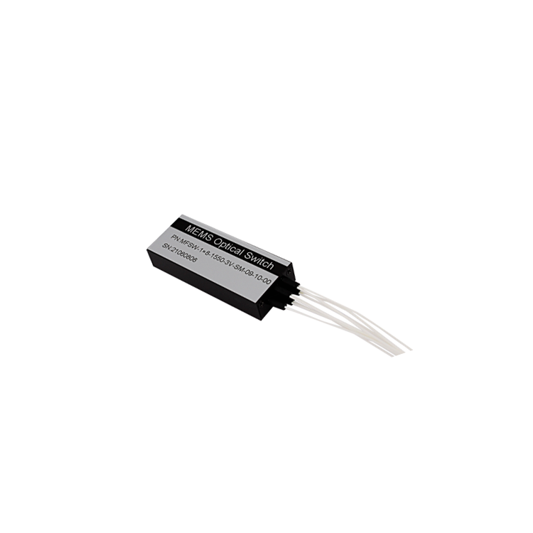
Exterior View & Installation
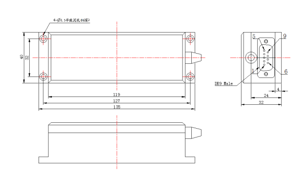
Figure 1 External Dimensions
When installing the optical switching module, the optical fiber must not be excessively bent (refer to Figure 2), so as not to affect the performance index of the optical switching module
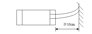
Figure 2 Schematic diagram of fiber optic installation
III. Schematic diagram of connecting lines
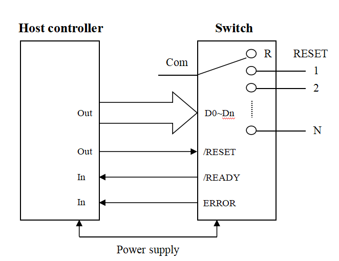
Fig. 3 Schematic diagram of connecting lines
Control Connection Description:
- /READY and ERROR connect to the input port of the control board, used to determine the state of the optical switch.
- /RESET connects to the output port of the control board, the controller output is low when switching the optical switch to channel 0 (i.e., no output); when high, the data bit is valid and switches to the data bit indicating the corresponding channel 1~2n.
- Data bits D0~Dn are connected to the output port of the control board. The valid data bits depend on the maximum number of channels N of the optical switch.
IV. Pin Definitions
Pin Number Pin Definitions Signal direction, type
(In/Out/Power) Function Description
1 D0 In Data bits.D3~D0 are binary numbers, D3 is high and D0 is low.4 data bits can control up to 16 channels of optical switch switching. Where, 0000b = channel 1; 0011b = channel 4. send data according to the actual number of channels of the optical switch when using.
2 D1 In 3 D2 In 4 D3 In 5 /Reset In A low reset to channel 0 and a high data bit is valid.
6 /Ready Out Low ready to reset or receive data.
7 Error Out A high level indicates an optical module operation error.
8 GND Power ground wire
9 DC 5V Power DC 5V, 1.0A operating power supply
V. Description of controls
1. Timing diagram
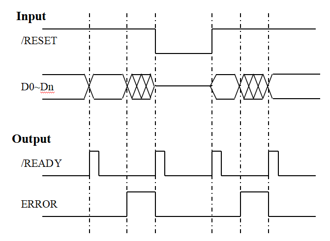
Timing diagram description:
- When /RESET is high, the data line D0~Dn value can switch the optical switch to the corresponding channel (1~2n) by varying within the range of non-overflow. During the optical switch switching process, /READY remains high until the optical switch switching action is completed.ERROR is output low when the data is not overflowed and high when the data is overflowed.
- When /RESET is low, the optical switch module resets to channel 0 regardless of the value of the data bit.
- Indicates overflow data, when the input data on the data bits exceeds the maximum number of channels of the optical switch. When the data bit on the data line overflows, /READY stays low and ERROR is output high.
2. Logic table (1 x 4 optical switch)
/RESET D3 D2 D1 D0 Channel 0 X X X X R 1 0 0 0 0 1 0 0 0 1 2 0 0 1 0 3 0 0 1 1 4
2. Logic table (1 x 4 optical switch)
VI. Instructions for use
1. The optical switch module is equipped with a control circuit interface, which is realized through a 9-pin socket to connect with the external control circuit, and the interface pin definition is shown in Table 1. Pay attention to the definition of each pin, the specific wiring refer to Figure 3.
2. The optical switch module is equipped with input and output fiber bundles, and the diameter of the input and output fibers is φ0.9mm. The input fiber (common fiber) is marked with COM logo, and the output fibers are marked with 1, 2, ......, and 4 logos, which indicate the four corresponding output fibers.
3. When power is turned on, the optical switch module will be reset automatically (R position in Fig. 3), and the optical path is in the disconnected state after reset, at which time it can be switched or reset through the data line or reset line.
4. Channel selection: Set/Reset high level, then select 1~16 channels through D3~D0. Since the optical switch module is 1×4, when the selected data exceeds channel 4, the module will not switch and set Error high until the correct data is input or reset, and then Error will be restored to low level.
5. Reset operation: Set/Reset low for reset operation, the optical switch module will be reset (R position in Figure 3), and the optical path is in the disconnected state after reset.
6. After the optical switching module is powered down, the optical switching module remains on the original channel, but the insertion loss will change.
7. When the optical switch module is processing data (during reset or channel switching), /Ready is high. When data processing is completed, /Ready is low. When incorrect data is entered, Error is high until correct data is entered or reset, then Error returns to low. For better control, the status of /Ready and Error need to be monitored to understand the operation of the optical switch module.
VII. Precautions
Before using the Optical Switch Module, please read the following rules carefully in order to avoid any damage to the Optical Switch Module:
1. Please clean the fiber optic end face of the connector with alcohol cotton before use. When not in use, please wear a dust cap to prevent dust or other dirt from contaminating or damaging the fiber optic end face. Damage or contamination of the fiber end face will affect the performance index of the optical switch module.
2. Strictly prohibit pulling, folding and twisting the optical fiber to avoid damage to the optical fiber.
3. Refer to Table 1 and Figure 3 for detailed pin definitions and wiring diagrams of the control interface to ensure correct wiring. Make sure that the wiring is correct, and then power up the unit after making sure that the wiring is correct.
4. The control signal level is TTL level.
5. When external circuits need to be changed, please turn off the power first, and then disconnect the control line of the module; the control line is prohibited to be hot-swapped with electricity.
6. When the optical switch module has an optical signal input, please do not look directly at the end face of the optical fiber. The laser radiation is not visible, but will cause damage to human eyes!
7. This device should be fireproof, shockproof, and avoid storing and working in an excessively humid environment.
This device is a precision optical device and should not be disassembled without authorization to avoid damage.
FSW-1×4 multi-mode optical switching module is a device with the role of optical path switching
Applications
FSW-1×4 multimode optical switching module is a functional device with the role of optical path switching, which is mainly used for the following purposes:
- Multiple optical monitoring in optical transmission system;
- LAN multi-light source/detector automatic switching, optical sensing multi-point dynamic monitoring system;
- Optical test system for optical fiber, optical device, network and field engineering optical cable testing;
- Optical device mounting.
Product Characteristics
- Low loss, high reliability;
- Simple parallel interface control;
- Modular design.
Product Performance
- Operating wavelength: 1450, 1550, 1650nm
- Fiber type: multimode (62.5/125)
- Optical interface: FC/APC(φ0.9)
- Fiber length: 1.0±0.05 m
- Insertion loss: ≤1.0dB
- Return loss: ≥30dB
- Polarization-related loss: ≤0.05 dB
- Wavelength dependent loss: ≤0.20 dB
- Temperature dependent loss: ≤0.20 dB
- Repeatability: ≤±0.05dB
- Channel crosstalk: ≥50dB
- Switching time: ≤10ms (neighboring channel sequential switching)
- Transmission optical power: ≤ 500mW
- Lifespan: ≥108 times
- Operating Temperature: -20~+70°C
- Storage Temperature: -40~+80°C
- Operating power supply: DC +5V, 1.0 A
Exterior View & Installation
Figure 1 External Dimensions
When installing the optical switching module, the optical fiber must not be excessively bent (refer to Figure 2), so as not to affect the performance index of the optical switching module
Figure 2 Schematic diagram of fiber optic installation
III. Schematic diagram of connecting lines
Fig. 3 Schematic diagram of connecting lines
Control Connection Description:
- /READY and ERROR connect to the input port of the control board, used to determine the state of the optical switch.
- /RESET connects to the output port of the control board, the controller output is low when switching the optical switch to channel 0 (i.e., no output); when high, the data bit is valid and switches to the data bit indicating the corresponding channel 1~2n.
- Data bits D0~Dn are connected to the output port of the control board. The valid data bits depend on the maximum number of channels N of the optical switch.
IV. Pin Definitions
| Pin Number | Pin Definitions | Signal direction, type (In/Out/Power) | Function Description |
|---|---|---|---|
| 1 | D0 | In | Data bits.D3~D0 are binary numbers, D3 is high and D0 is low.4 data bits can control up to 16 channels of optical switch switching. Where, 0000b = channel 1; 0011b = channel 4. send data according to the actual number of channels of the optical switch when using. |
| 2 | D1 | In | |
| 3 | D2 | In | |
| 4 | D3 | In | |
| 5 | /Reset | In | A low reset to channel 0 and a high data bit is valid. |
| 6 | /Ready | Out | Low ready to reset or receive data. |
| 7 | Error | Out | A high level indicates an optical module operation error. |
| 8 | GND | Power | ground wire |
| 9 | DC 5V | Power | DC 5V, 1.0A operating power supply |
V. Description of controls
1. Timing diagram
Timing diagram description:
- When /RESET is high, the data line D0~Dn value can switch the optical switch to the corresponding channel (1~2n) by varying within the range of non-overflow. During the optical switch switching process, /READY remains high until the optical switch switching action is completed.ERROR is output low when the data is not overflowed and high when the data is overflowed.
- When /RESET is low, the optical switch module resets to channel 0 regardless of the value of the data bit.
- Indicates overflow data, when the input data on the data bits exceeds the maximum number of channels of the optical switch. When the data bit on the data line overflows, /READY stays low and ERROR is output high.
2. Logic table (1 x 4 optical switch)
| /RESET | D3 | D2 | D1 | D0 | Channel |
|---|---|---|---|---|---|
| 0 | X | X | X | X | R |
| 1 | 0 | 0 | 0 | 0 | 1 |
| 0 | 0 | 0 | 1 | 2 | |
| 0 | 0 | 1 | 0 | 3 | |
| 0 | 0 | 1 | 1 | 4 |
2. Logic table (1 x 4 optical switch)
VI. Instructions for use
1. The optical switch module is equipped with a control circuit interface, which is realized through a 9-pin socket to connect with the external control circuit, and the interface pin definition is shown in Table 1. Pay attention to the definition of each pin, the specific wiring refer to Figure 3.
2. The optical switch module is equipped with input and output fiber bundles, and the diameter of the input and output fibers is φ0.9mm. The input fiber (common fiber) is marked with COM logo, and the output fibers are marked with 1, 2, ......, and 4 logos, which indicate the four corresponding output fibers.
3. When power is turned on, the optical switch module will be reset automatically (R position in Fig. 3), and the optical path is in the disconnected state after reset, at which time it can be switched or reset through the data line or reset line.
4. Channel selection: Set/Reset high level, then select 1~16 channels through D3~D0. Since the optical switch module is 1×4, when the selected data exceeds channel 4, the module will not switch and set Error high until the correct data is input or reset, and then Error will be restored to low level.
5. Reset operation: Set/Reset low for reset operation, the optical switch module will be reset (R position in Figure 3), and the optical path is in the disconnected state after reset.
6. After the optical switching module is powered down, the optical switching module remains on the original channel, but the insertion loss will change.
7. When the optical switch module is processing data (during reset or channel switching), /Ready is high. When data processing is completed, /Ready is low. When incorrect data is entered, Error is high until correct data is entered or reset, then Error returns to low. For better control, the status of /Ready and Error need to be monitored to understand the operation of the optical switch module.
VII. Precautions
Before using the Optical Switch Module, please read the following rules carefully in order to avoid any damage to the Optical Switch Module:
1. Please clean the fiber optic end face of the connector with alcohol cotton before use. When not in use, please wear a dust cap to prevent dust or other dirt from contaminating or damaging the fiber optic end face. Damage or contamination of the fiber end face will affect the performance index of the optical switch module.
2. Strictly prohibit pulling, folding and twisting the optical fiber to avoid damage to the optical fiber.
3. Refer to Table 1 and Figure 3 for detailed pin definitions and wiring diagrams of the control interface to ensure correct wiring. Make sure that the wiring is correct, and then power up the unit after making sure that the wiring is correct.
4. The control signal level is TTL level.
5. When external circuits need to be changed, please turn off the power first, and then disconnect the control line of the module; the control line is prohibited to be hot-swapped with electricity.
6. When the optical switch module has an optical signal input, please do not look directly at the end face of the optical fiber. The laser radiation is not visible, but will cause damage to human eyes!
7. This device should be fireproof, shockproof, and avoid storing and working in an excessively humid environment.
This device is a precision optical device and should not be disassembled without authorization to avoid damage.