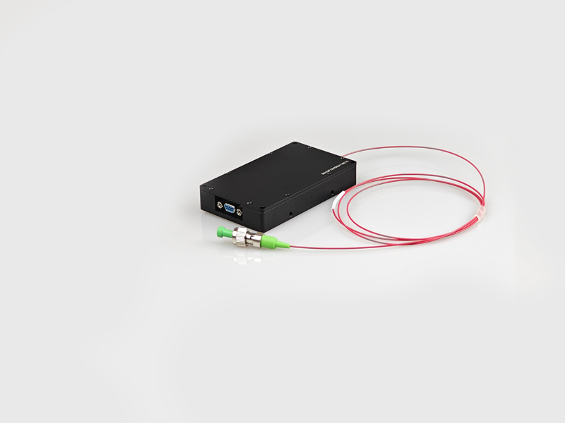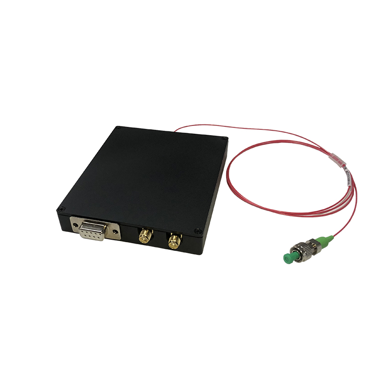
1550nm Narrow Linewidth FMCW Tunable Laser Module (Ultra Low RIN)
1550nm Narrow Linewidth FMCW Tunable Laser Module with Ultra Low RIN Noise and Excellent FM Performance for Wide Range of FMCW Lidar Applications.
 Huang
Email: Hqy@ybphotonics.com
Huang
Email: Hqy@ybphotonics.com
Product Introduction
This 1550nm Narrow Linewidth FMCW Tunable Laser Module features ultra-low RIN noise and excellent frequency modulation (FM) performance, engineered for FMCW LiDAR and radar applications. With narrow linewidth, wide tuning range, stable wavelength, high output power and low power consumption, it is a high-performance semiconductor laser module suitable for coherent detection, fiber optic sensing, medical photonics, scientific research equipment and 3D mapping. Customization is available for specific application requirements.
Core Features
- 1550nm Core Wavelength : Stable center wavelength, perfect for FMCW LiDAR/radar and fiber optic sensing systems
- Ultra-Narrow Linewidth : ≤15kHz Lorentz linewidth (tested by delayed autocorrelation), low signal distortion
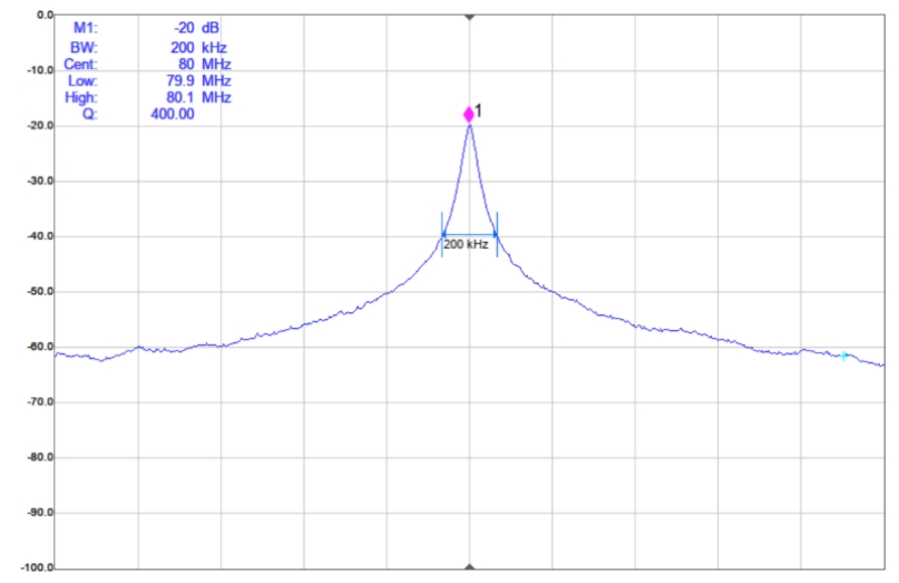
- Ultra-Low RIN Noise : ≤-140dB/Hz relative intensity noise, high signal-to-noise ratio for precision detection
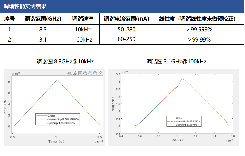
- High Tuning Linearity : ≥99.99% basic linearity (up to 99.999% for specific ranges), no pre-calibration required
- Dual Wide Tuning Ranges : Configurable tuning ranges and rates, matching diverse FMCW application needs
- High Performance Indices : 60dB SMSR, 20dB minimum PER, 50dB optical isolation for stable output
- Compact & Easy Integration : Small form factor, DC 5V/3A low voltage supply, standard Type-C/SMA/FC/PC interfaces
- Multiple Protections : Built-in interlock safety control, over-temperature/under-temperature protection for reliable operation
Applications
- FMCW LiDAR & FMCW Radar systems
- Coherent optical detection equipment
- Distributed fiber optic sensing systems
- Medical photonics & biomedical detection
- Scientific research & laboratory optical equipment
- 3D mapping & remote sensing systems
- High-precision optical communication systems
Technical Specifications
| Params | symbol | test condition | Min. | Type. | Max. | Unit |
|---|---|---|---|---|---|---|
| center wavelength | NC | CW | 1550 | nm | ||
| Wavelength adjustable range I | CW | 2 | GHz | |||
| Wavelength Adjustable Rate I | CW | 100 | kHz | |||
| Wavelength adjustable range II | CW | 5 | GHz | |||
| Wavelength adjustable rate II | CW | 30 | kHz | |||
| Tuning Linearity | 99.99% | |||||
| optical power out of a fiber | Pf | CW | 10 | mW | ||
| Lorentz line width* | FWHM | CW | 15 | kHz | ||
| relative intensity noise | RIN | -140 | dB/Hz | |||
| Side mode rejection ratio | SMSR | CW | 60 | dB | ||
| off-set extinction ratio | PER | CW | 20 | dB | ||
| optical isolation | ISO | 50 | dB | |||
| operating temperature | To | 0 | 60 | ℃ | ||
| Operating humidity | % | 5 | 85 |
* Delayed autocorrelation method for testing Lorentzian linewidths
Product Performance Chart
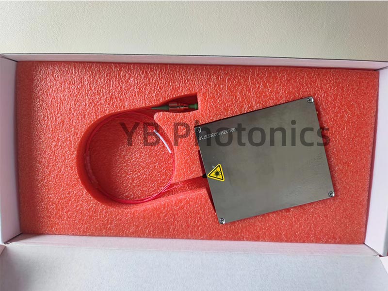
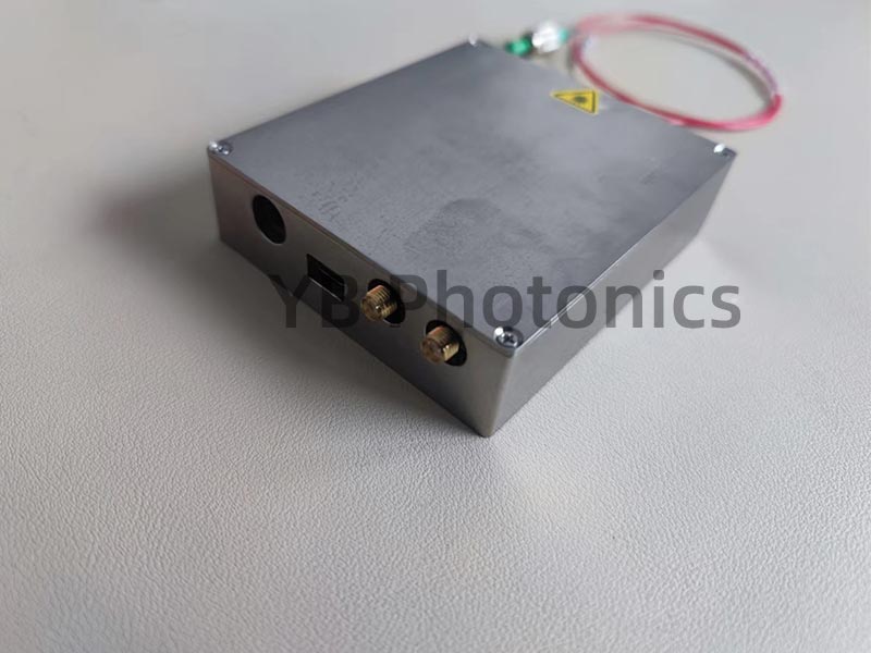
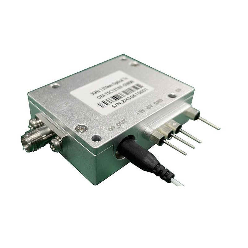
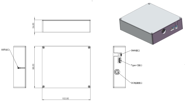
Product Electrical and Appearance Parameters
| item | Parameter Configuration | Unit |
|---|---|---|
| Exterior Dimensions | L×W×H=102×88×26 | mm |
| Built-in pigtail type | PMF | |
| connectors | FC/PC Flange | |
| power supply | DC 5V/3A | |
| data interface | Type-C | |
| Synchronous Signal Interface | SMA | |
| safety control | Interlock |
Order Info
UNL-C-T-M-CXX-X
| UNL-C-T-M- | Wavelength | Sweep Configuration |
|---|---|---|
| C34: 1550.12 | 1:8.3G@10kHz | |
| 2:2G@100kHz | ||
| 3:3.1G@100kHz | ||
| 4:5G@30kHz | ||
| 5:Other |
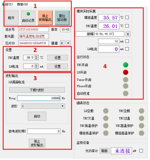
Upper computer software interface description
1: Laser driver board startup and shutdown function
2: Setting laser LD drive current and TEC temperature function (range setting limit: LD maximum 250mA, TEC 10-35℃)
3: LD arbitrary modulation waveform download, modulation frequency setting, and tuning output start and stop
4: PCB temperature, LD current, TEC temperature/current real-time monitoring (green means TEC temperature has stabilized)
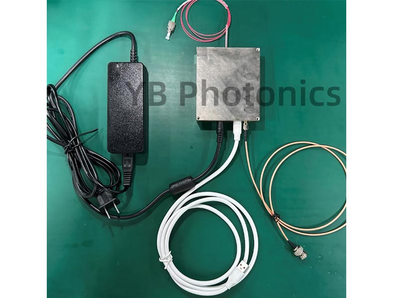
Hardware connection for tunable laser modules
The following figure
1) Connect the adjustable laser module to the computer (USB port) with the included USB special interface cable.
2) Connect the laser signal output (FC/APC) with optical fiber.
3) If necessary, connect the modulated waveform synchronization signal output (SMA) to the system under test;
4) Finally, power up the tunable laser module with the supplied power adapter.