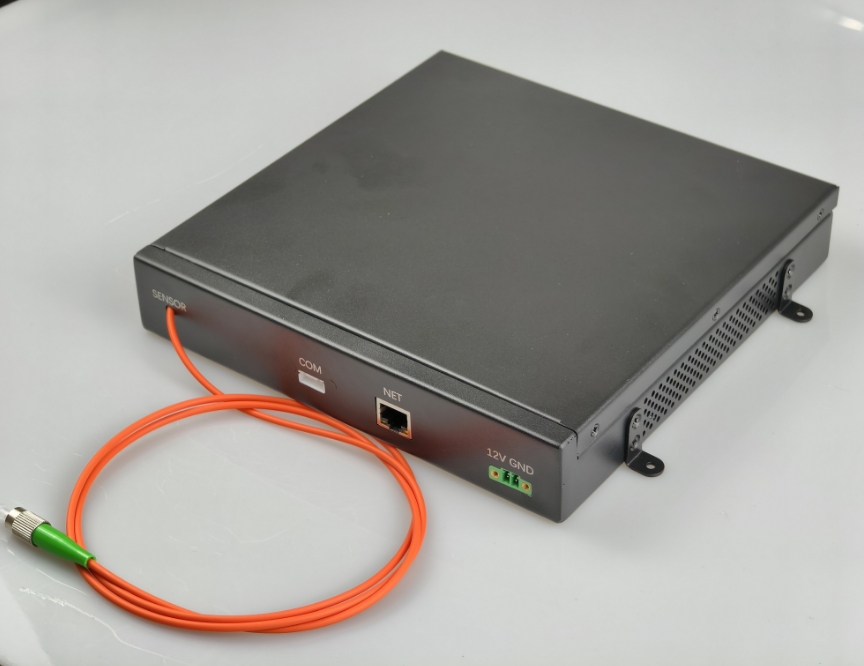
GY-DTS-M DTS Integrated Module - Laser+WDM+APD+DAQ | Gigabit Ethernet UDP
GY-DTS-M is a DTS integrated module, which integrates laser+WDM+APD+acquisition card, greatly simplifying the complexity of the system, and adopts the Gigabit Ethernet UDP protocol to collect data, and the module can output Stokes light and anti-Stokes light signals.
 Huang
Email: Hqy@ybphotonics.com
Huang
Email: Hqy@ybphotonics.com
Product Overview
The GY-DTS-M DTS (Distributed Temperature Sensing) Integrated Module is a high-performance, all-in-one optical sensing module that pre-integrates Laser, WDM (Wavelength Division Multiplexer), APD Photodetector, and High-Speed DAQ Card into a compact design. This highly integrated architecture greatly simplifies the hardware complexity of DTS systems, eliminating the need for separate component wiring and debugging.
The module adopts Gigabit Ethernet UDP protocol for high-speed data acquisition and transmission, and directly outputs Stokes and anti-Stokes optical signals—the core signals for DTS temperature demodulation. Users only need to focus on the R&D and development of DTS host demodulation software, reducing 80% of DTS system hardware development work and accelerating project progress.
Core Selling Points
- ✅ All-in-One Integration: Pre-integrated Laser+WDM+APD+DAQ, no complex hardware assembly
- ✅ High-Speed Data Transmission: Gigabit Ethernet with UDP protocol, easy data reading & processing
- ✅ High Measurement Accuracy: ±1℃ temperature accuracy & end-of-line noise (tested on 5000m fiber)
- ✅ Flexible Configuration: Adjustable pulse width (5-120ns) & repetition rate (5-20kHz)
- ✅ Customizable: Pigtail type/connector can be customized as customer requirements
- ✅ Wide Temperature Adaptation: -15℃~55℃ operating temperature, industrial-grade stability
- ✅ Free Global Shipping: No extra shipping cost to any country/region worldwide
- ✅ Professional Technical Support: 24/7 guidance for software-hardware integration
Key Features
- Highly integrated compact design: Integrates all core DTS optical/electrical components, small module size for easy system integration
- Gigabit Ethernet UDP communication: Standard network protocol, simple and fast data reading, compatible with mainstream industrial control systems
- Dual optical signal output: Directly outputs Stokes and anti-Stokes light signals, the core for DTS temperature demodulation
- Flexible parameter adjustment: Repetition rate (5-20kHz) and pulse width (5-120ns) adjustable for different DTS detection requirements
- High sampling performance: 250MSps sampling rate, 0.4m sampling resolution, ensuring high spatial resolution of temperature sensing
- Industrial-grade reliability: Wide operating temperature range (-15℃~55℃), low power consumption (13W typical), stable long-term operation
- Standard & customizable pigtail: 62.5/125 multimode fiber with FC/APC connector (default), other connectors/pigtail types customizable
- Modbus RTU slave protocol: Standard laser communication protocol, easy to integrate with DTS host control systems
Target Users
The GY-DTS-M is specially designed for DTS system R&D enterprises and research institutions that meet the following requirements:
- Have independent DTS demodulation software development capabilities
- Pursue cost optimization for DTS system hardware
- Need to simplify DTS system wiring and hardware debugging work
- Require high-precision, industrial-grade DTS core sensing modules for fiber optic temperature sensing projects
Technical Specifications
| params | Unit | Min. | Type. | Max. |
|---|---|---|---|---|
| center wavelength | nm | - | 1550.12 | - |
| spectral widt( 20dB) | nm | - | 0.3 | 1 |
| Output peak optical power | W | 30 | ||
| repetition rate | kHz | 5 | - | 20 |
| pulse width | ns | 5 | - | 120 |
| sampling rate | MSps | 250 | ||
| sampling resolution | m | 0.4 | ||
| operating temperature | ℃ | -15 | - | 55 |
| Storage temperature | ℃ | -40 | - | 85 |
| power wastage | W | - | 13 | |
| operating voltage | V | 9 | 12 | 13 |
| data output interface | / | Gigabit Ethernet port, UDP protocol | ||
| Laser communication protocols | / | Modbus RTU slave | ||
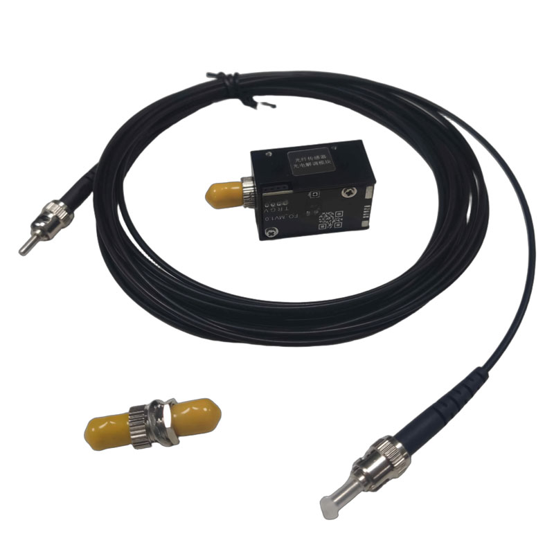
| Pigtail Type | / | 62.5/125 multimode fiber, FC/APC connector (or customer specified) | ||
| Output Fiber Length | m | ≥1 | ||
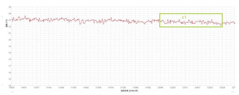
To evaluate the performance of this module, we developed a demodulation software. The following test data was obtained.
Test fiber optic cable length: 5000 meters
| Parameter | Value |
|---|---|
| End-of-line noise | ±1℃ |
| Temperature Accuracy | ±1℃ |
| Spatial resolution | 1.2m |
End-of-line noise: Lowest point in the green box at 22°C, highest point at 24°C, with noise level tolerance of ±1°C.
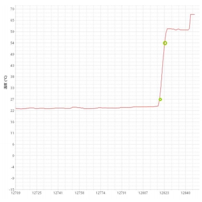
Spatial Resolution: Refers to the effective spatial distance along the fiber length during sensing. At the disturbance location, the fiber length corresponding to the distance between the fiber segments where the measured step change value of the disturbance information falls between 10% and 90% constitutes the spatial resolution fiber length. As shown below: The temperature measurement coil's 90% corresponds to coordinates (12823, 54), while 10% corresponds to coordinates (12820, 27).
Therefore, the spatial resolution = (12823 - 12820) × 0.4 = 1.2 m.
Temperature accuracy, as shown in the figure below:
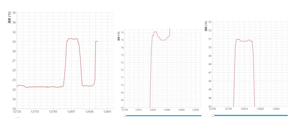
| Water Bath Temperature (°C) | Our demodulation software readings (°C) |
|---|---|
| 30 | 30(±1) |
| 50 | 50(±1) |
| 70 | 70(±1) |
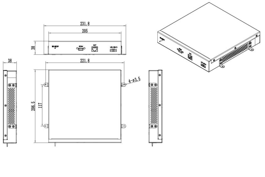
Dimensions
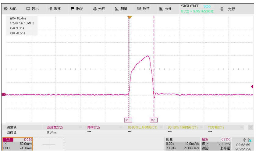
Pulse Width Modulation Example Diagram
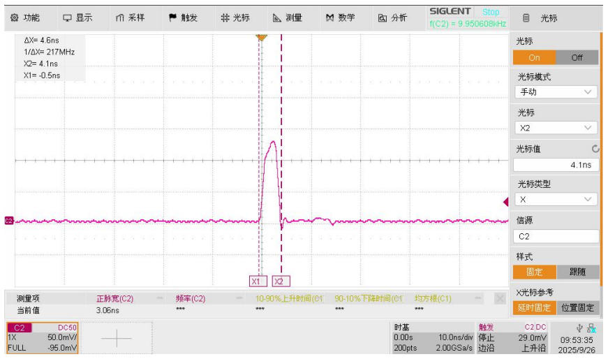
1. With the frequency set to 10 kHz and pulse width to 5 ns, the laser module connected to a photodetector displays the following waveform on the oscilloscope:
2. Set the frequency to 10 kHz and the pulse width to 10 ns. After connecting the laser module to the photodetector, the oscilloscope display appears as follows: