DAS Integration Module and DAQ Installation and Wiring Tutorials
DAS Integration Module and DAQ Installation and Wiring Tutorials, Distributed fiber optic acoustic sensing system installation and wiring tutorial, DAS integrated module and DAQ board wiring steps and precautions.
Video Link:
Subtitles in the video
Before installing the DAS module
please read the user's manual of the DAS module carefully
Then operate
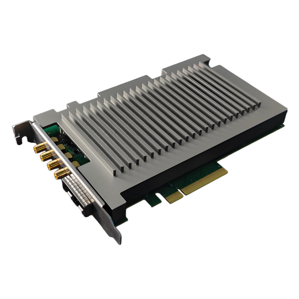
This is our DAS dedicated capture card
the interface of the capture card is PCIe x8
So the capture card needs to be plugged into our computer to work
Therefore, before installing a DAS system
please prepare a computer with a PCIe x8 socket
Then plug the capture card into your computer
Follow the capture card driver installation instructions we provide
Install the driver on your computer first
Then the capture card has 4 ports
the top 2 are CH0, CH1
which represent the data that can be captured from 2 channels
Then Trig is the trigger output interface
and CLK is the clock synchronization interface
After installing the driver of the capture card
we will wire the DAS module
Before wiring, please check whether all material accessories are complete
Since the DAS integration module is 5V powered
and the acousto-optic modulator is 24V powered
So our power module needs 5V and 24V power supply at the same time
If you do not have a suitable power module
you can contact us for recommendations
This is the power module
the input is 220V
L is the fire wire brown
N is the zero wire blue
and the ground wire is yellow and green
Here we need to pay attention:
please do not power up the computer module
before all the wiring is done
From the computer module label
we can see
V1 terminal: 5V
V1 terminal: 5V
V2 terminal: 24V
COM terminal for ground
This is the DAS integrated module
from left to right
OUT1 indicates the output of channel 1
OUT2 indicates the output of channel 2
Then there are 2 Senser fiber optic cable outlets
corresponding to Sender1 for channel 1
and Sensor2 for channel 2
If it is a single channel
we just need to connect the OUT1 interface with the CH1 interface of the capture card with RF cable
AOM RF is the acoustic-optic modulator drive signal input
then the indicator light and power supply communication terminals
DAS integrated modules are basically factory optimized
so you can just connect the power supply port
find 2 wires
V port to the 5V terminal of the power module
G port to the COM terminal of the power module
This is the acousto-optic modulator driver
because the power supply of the acousto-optic modulator driver is 24V
so the positive terminal of the acousto-optic modulator driver needs to be connected to the 24V terminal of the power module
and the negative terminal is connected to the COM terminal of the power module
Then the acousto-optic modulator has one RF input port
and one RF output port
The RF input port is connected to the Trig trigger output port of the capture card with an RF cable
the RF output port is connected to the AOM RF of the DAS integration module with an RF cable
The rest is to connect the sensing fiber optic cable
Since our DAS module outgoing fiber connector is FC/APC connector (green connector)
the interface of the sensing fiber optic cable you prepare must also be FC/APC connector (green connector)
Connecting via an FC adapter
At this point
all wiring has been completed
re-check again for errors
If there is no error
you can connect the power module to 220V power
Then open our DEMO demo program from your computer
to see if it's working correctly!