Introduction to the Principles and Components of Distributed Fiber Optic Temperature Measurement Systems (DTS)
Introduction to the Principles and Components of Distributed Fiber Optic Temperature Measurement Systems (DTS), The video introduces the principles of a distributed fiber optic Raman temperature measurement system and the components needed to make up the system.
Video Link:
Subtitles in the video
1
00:00:00,100 --> 00:00:04,033
Distributed Fiber Optic Raman Temperature Measurement DTS system
2
00:00:04,166 --> 00:00:08,266
is based on the optical time domain reflection (OTDR)
3
00:00:08,400 --> 00:00:12,866
principle of optical fibers and the Raman scattering effect of optical fibers
4
00:00:13,000 --> 00:00:16,466
The laser pulse interacts with the fiber molecules
5
00:00:16,466 --> 00:00:18,066
and a variety of scattering occurs
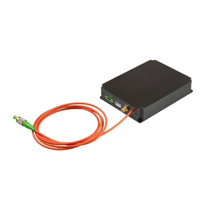
6
00:00:18,166 --> 00:00:19,666
such as Rayleigh scattering
7
00:00:19,700 --> 00:00:22,733
Brillouin scattering and Raman scattering
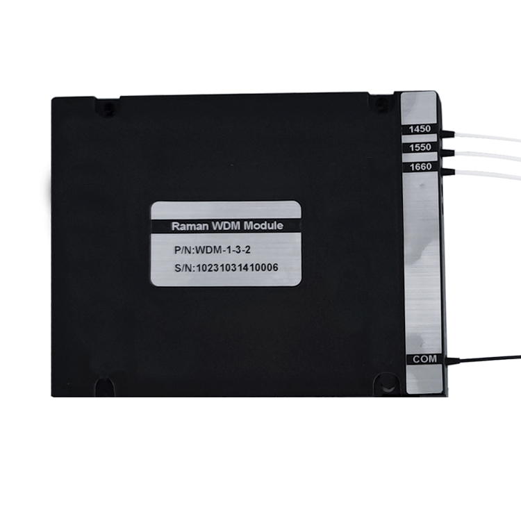
8
00:00:22,833 --> 00:00:26,433
Raman scattering is due to the thermal vibration of the fiber optic molecules
9
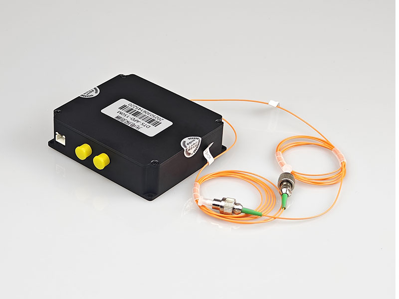
00:00:26,466 --> 00:00:30,533
which produces a light-Stokes light that is longer than the wavelength of the light source
10
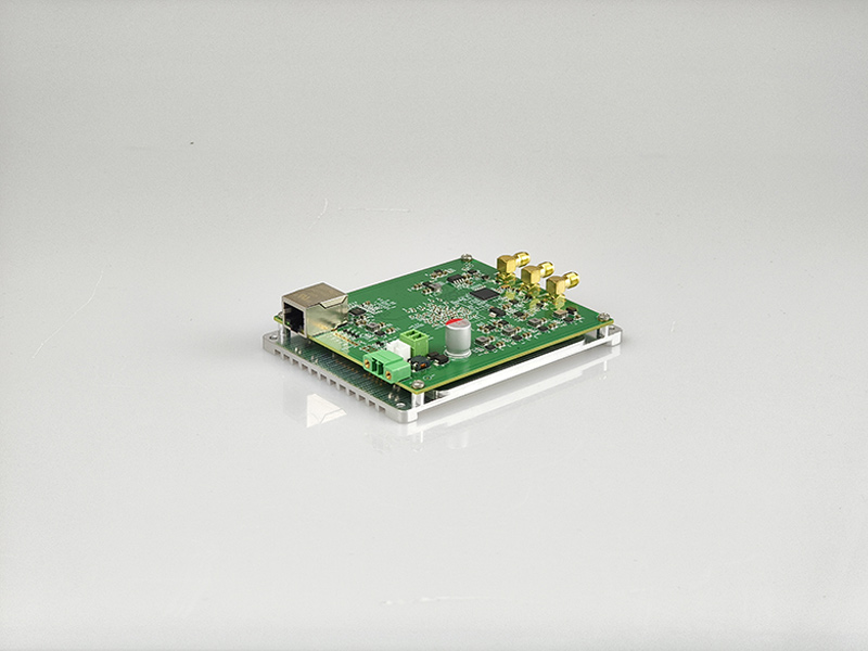
00:00:30,600 --> 00:00:36,100
and a Anti-Stokes light that is shorter than the wavelength of the light source
11
00:00:36,100 --> 00:00:38,800
The fiber is modulated by the external temperature
12
00:00:38,800 --> 00:00:42,966
causing the Anti-Stokes light intensity in the fiber to change
13
00:00:42,966 --> 00:00:47,833
Anti-Stokes to Stokes ratio provides an absolute indication of temperature
14
00:00:47,933 --> 00:00:53,466
the use of this principle to achieve the distributed measurement of the temperature field along the optical fiber
15
00:00:53,500 --> 00:00:59,466
combined with high-quality pulsed light source and high-speed signal acquisition and processing technology
16
00:00:59,466 --> 00:01:04,866
we can get the accurate temperature value of all points along the fiber
17
00:01:04,966 --> 00:01:07,000
According to the above principle
18
00:01:07,000 --> 00:01:09,766
we look at the specific realization of the system
19
00:01:10,000 --> 00:01:13,933
First of all, the DTS system needs a pulsed laser
20
00:01:13,933 --> 00:01:17,033
the output light is 1550nm
21
00:01:17,133 --> 00:01:20,066
the typical pulse width is 10ns
22
00:01:20,133 --> 00:01:22,733
peak power: 10~30W
23
00:01:22,733 --> 00:01:25,233
the trigger mode is: external trigger
24
00:01:25,233 --> 00:01:30,233
and the pigtail type is a multimode fiber of 62.5/125
25
00:01:30,366 --> 00:01:33,400
The output port of the pulsed laser
26
00:01:33,400 --> 00:01:37,300
is connected to the 1550 port of the 1x3 Raman WDM module
27
00:01:37,300 --> 00:01:42,266
then the temperature measurement fiber optic cable is connected to the COM port of the WDM
28
00:01:42,266 --> 00:01:50,133
and the remaining 1450 and 1660 ports are connected to the two input ports of the dual-channel APD respectively
29
00:01:50,133 --> 00:01:53,433
The dual-channel APD photoelectric converter
30
00:01:53,433 --> 00:01:57,133
converts the anti-Stokes and Stokes light into electrical signals
31
00:01:57,200 --> 00:02:00,400
the electrical signals are output through the SMA interface
32
00:02:00,433 --> 00:02:05,200
and connected to the two acquisition channels of the acquisition card with RF cables
33
00:02:05,366 --> 00:02:08,966
The capture card has an integrated signal trigger function
34
00:02:08,966 --> 00:02:15,100
Connect the trigger interface to the laser's SMA trigger input via the RF cable
35
00:02:15,133 --> 00:02:17,966
This completes all wiring
36
00:02:18,000 --> 00:02:21,833
The acquisition card has a built-in averaging algorithm
37
00:02:21,866 --> 00:02:25,800
The data collected by the two channels of the acquisition card
38
00:02:25,933 --> 00:02:28,600
can be plotted as two real-time curves
39
00:02:28,733 --> 00:02:31,033
The ratio of the two curves
40
00:02:31,033 --> 00:02:33,866
has an approximately linear relationship with the temperature
41
00:02:33,866 --> 00:02:37,900
By calibrating the temperature of the test fiber optic cable
42
00:02:38,066 --> 00:02:42,266
we can obtain the relationship between the temperature and the ratio
43
00:02:42,300 --> 00:02:45,966
realize the function of temperature measurement of fiber optic cables
44
00:02:46,000 --> 00:02:46,933
Of course
45
00:02:46,933 --> 00:02:50,866
the reality also needs to take into account the length of the fiber optic cable、
46
00:02:50,966 --> 00:02:57,566
optical power、attenuation and other factors, and do the corresponding compensation algorithm
47
00:02:57,666 --> 00:03:01,366
To realize the high precision DTS temperature measurement system
48
00:03:01,533 --> 00:03:03,766
it still needs technology
49
00:03:03,766 --> 00:03:10,066
We have made all the equipment for the DTS system mentioned above into a hardware development kit
50
00:03:10,166 --> 00:03:12,133
so please inquire if you are interested.