What is the bandwidth of a photodetector Video
What is the bandwidth of a photodetector Video, Video presentation explaining what the bandwidth of a photodetector is and how to select the right DAQ for a photodetector system
Video Link:
Subtitles in the video
What is the bandwidth of a photodetector?
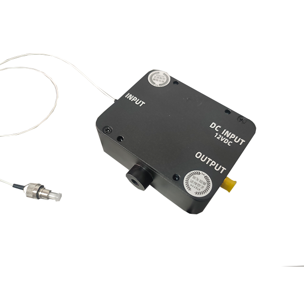
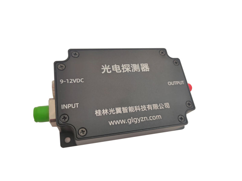
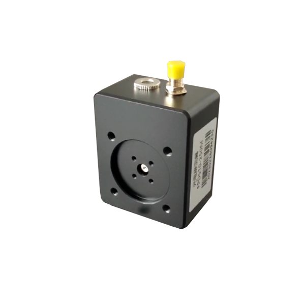
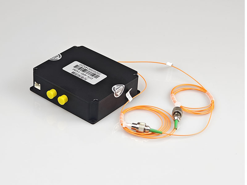
The main function of a photodetector is to convert an optical signal into an electrical signal.
We usually use the amount of optical power to measure the strength of the optical signal entering the detector, and the output electrical signal is the voltage value.
We often encounter light with continuous light and pulsed light, continuous light is the size of the light power does not change, has been continuous.
Continuous light is converted by our photodetectors to a stable voltage.
Pulsed light, on the other hand, is characterized by the on-off of light, and the output of such light after conversion by our photodetectors corresponds to a high level and a low level.
Since the input light is continuously fed in, our photodetector also converts the light signal into an electrical signal in real time.
If we record the output voltage value over time, the horizontal coordinate represents the time and the vertical coordinate is the voltage value.
A time domain waveform signal can be obtained. Simply analyzing this waveform signal we can obtain the bandwidth value of the signal.
1·Assuming that the waveform graph is a sine wave, then we can assume that the maximum frequency of the sine wave is the bandwidth of the signal.
2.If the waveform graph is a square wave, then we can calculate the approximate bandwidth of the signal from the maximum frequency * 4 to 5 times.
3.Or you know the rise time of your signal, and by using 0.35/rise time, you can estimate the bandwidth size.
Our photodetector specifications will list the bandwidth parameter, which indicates the detector's detector capability, for example, a bandwidth of DC~100M means that the detector can detect signals from DC to 100M.So your actual signal needs to be in the range of DC~100M to be fully detected.
Therefore, when we choose a detector, we need to evaluate the size of our optical signal bandwidth; then check the specification of the photodetector to find the bandwidth parameter.
We need to make sure that the actual optical signal is within the detection bandwidth of the detector. When we have selected the detector, we have also evaluated the signal bandwidth for our application. So how should we choose a capture card?
The sampling rate of the capture card has to be chosen based on our actual signal bandwidth, not the bandwidth capability of the detector.
According to the sampling theorem: it is necessary to 2 times the frequency of the actual voltage signal, but 2 times can not be well restored to our signal curve, so we in order to restore the signal curve more real, the sampling rate of the acquisition card is best to sample the frequency of the signal 5-8 times. That is, if your signal is 5M, it is recommended to use 25M or more sampling rate acquisition card.
Here is an example to illustrate: the experimental device has a high-speed rotation of the fan, there is a small hole in the fan. Then we use a laser to shine light onto the fan, when the small hole on the fan and the laser beam into a straight line, the light will be through the small hole to the photodetector behind the fan.
The photodetector then converts the light signal into an electrical signal in real time, which is connected to an oscilloscope, where the waveform of the voltage value output from the detector can be seen.
So how is the bandwidth determined in this experimental setup? In this setup, the laser emits a beam at a fixed position, and the fan is rotated so that the detector behind it receives light input when the laser hits the hole. If the detector receives no light, the output voltage is "zero", and when light is received, the output voltage is a value greater than zero, assuming 2V.
The time t1 it takes for the fan to make one revolution is the interval between the two peaks on the oscilloscope's signal graph, and we also call this interval the period/reclocking of the signal. Then look at a single peak, from "zero" to the peak of the time required t2, we call the rise time. Using the previous calculation of bandwidth = 0.35 divided by rise time, we can calculate the bandwidth of our signal.t3 is the duration of the light through the hole, i.e., the pulse width.


