How to configure a pulsed laser for DTS temperature sensing
Pulse laser model
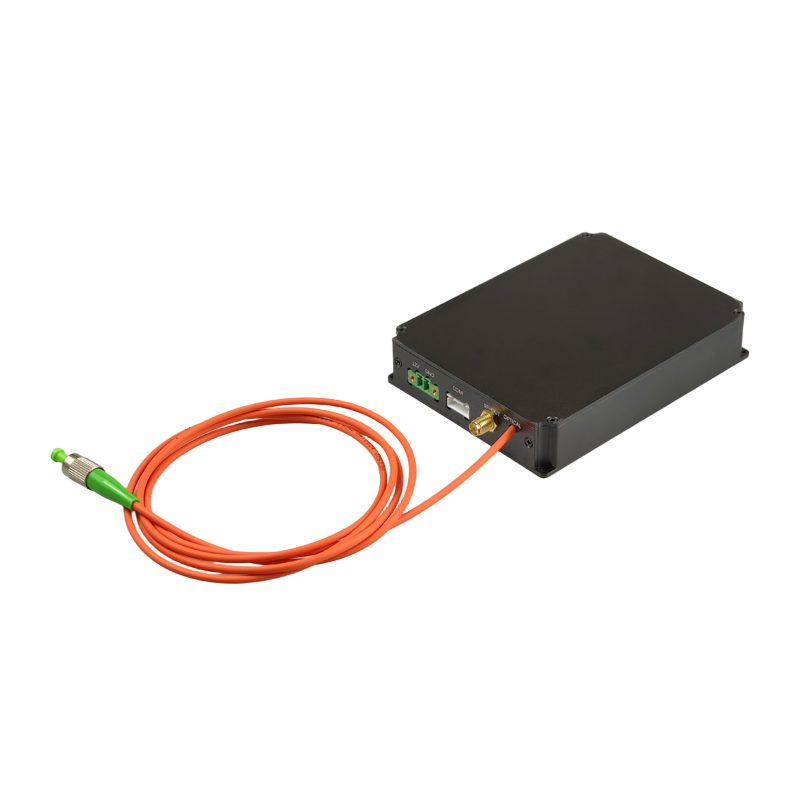
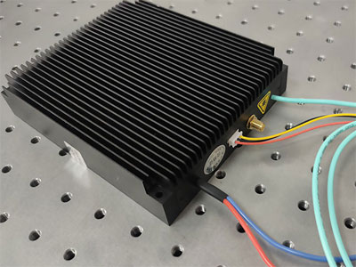
We chose YB Photonics' DTS-LASER-1550-30 as the pulsed laser for DTS temperature sensing.This laser module is released by YB Photonics specifically for distributed fiber optic temperature sensing systems and has the following features:
- High peak value output
- Adjustable pulse width
- High stability and high reliability
Specific product details parameters, view.
Trigger method
When ordering the DTS-LASER-1550-30 nanosecond pulsed laser, you need to choose the trigger method, there are two ways to choose between external trigger and internal trigger. Choose external trigger, that is, the customer's own external trigger signal into the SMA interface, using external pulse signal to set the laser pulse width and frequency.
Connection to the upper computer software
The laser module communicates with RS232, so we first need to connect the RS232 communication port to our PC.
Then open the host software of our pulse laser. Click to install it as shown below:
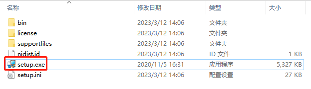
After successful installation, we open the upper software of the pulsed laser.
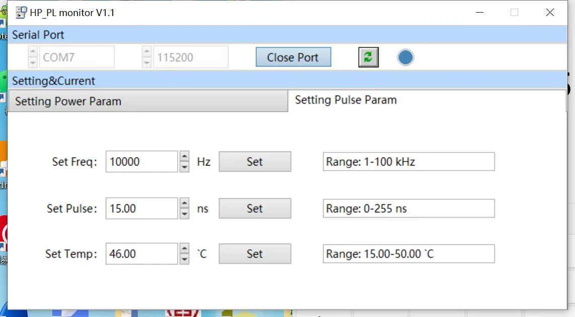
If you ordered a laser module with an external trigger, you can leave the "setting Pulse Param" page alone. Just configure the "Setting Power Param" page.
Parameter Setting
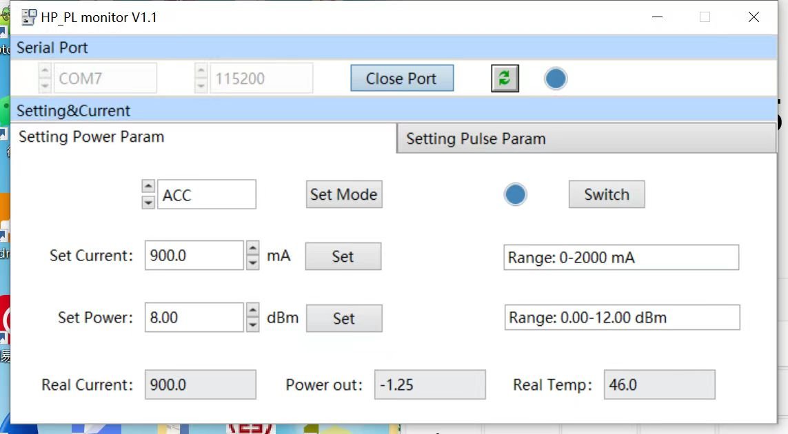
First in ACC mode debugging normal after, and then change the APC mode, ACC itself is available, but APC is automatic power control, in APC mode is not affected by temperature.
Switching between ACC and APC: Please set it to ACC mode during initial debugging, when the frequency/pulse width/pump current is adjusted to a suitable value, display the PD detection value in Power out, fill the PD detection value into Set Power and click Set, and finally change ACC mode to APC mode and click Set Mode.
Power out is the actual value of PD detection, and Set Power is the locked PD detection value. When switching to APC mode, the locked PD detection value will be used as the base for automatic power compensation.
APC mode setting steps
- ACC mode, give the external trigger frequency, according to the customer's own needs, adjust the module pulse width and pump current to the appropriate value.
- at this time, a value (such as 3dbm) will appear in power out, put this value (3dbm) in set power, then click SET, and then switch ACC mode to APC mode that completes the setting.