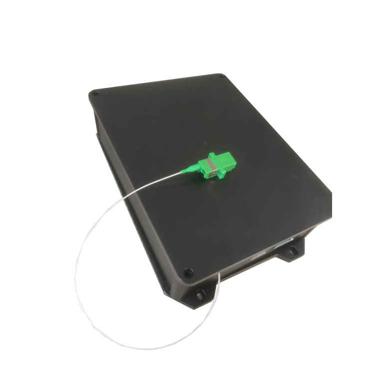
Tunable Laser Minimum Step 1pm C-Band 1Hz/1000Hz/2000Hz
Fast scanning speed, under 10pm step size, the fastest 1s to complete the C-band scanning
 Huang
Email: Hqy@ybphotonics.com
Product Info
Introduction
Tunable lasers are lasers in which the wavelength of the laser output can be continuously varied within a certain range. These lasers are used in a wide range of applications, including spectroscopy, photochemistry, medicine, biology, integrated optics, pollution monitoring, semiconductor material processing, information processing and communications.
Product Description:
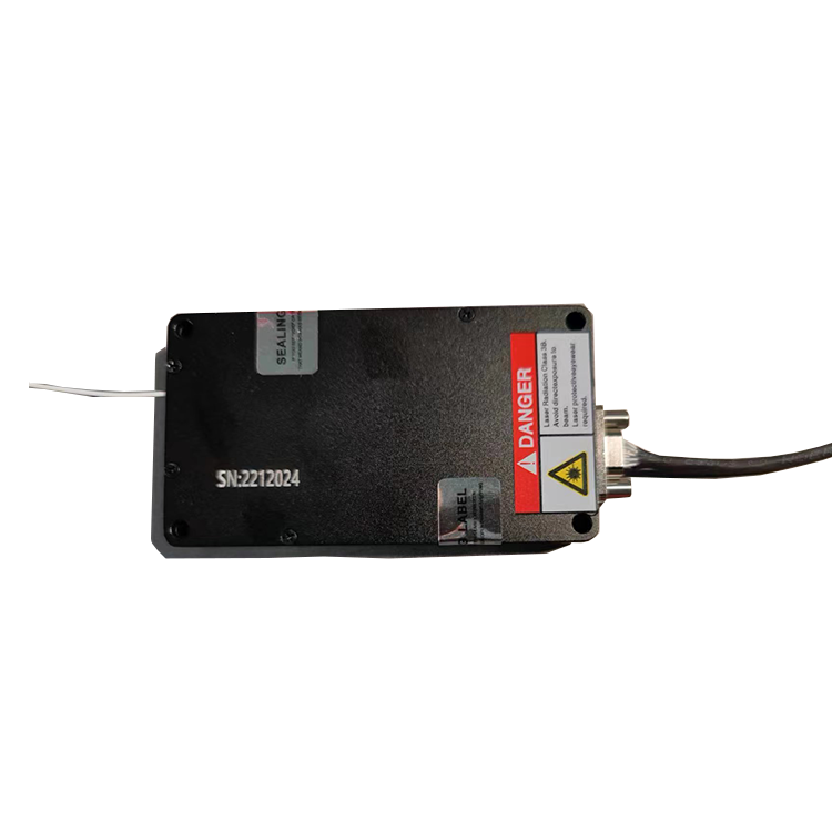
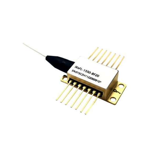
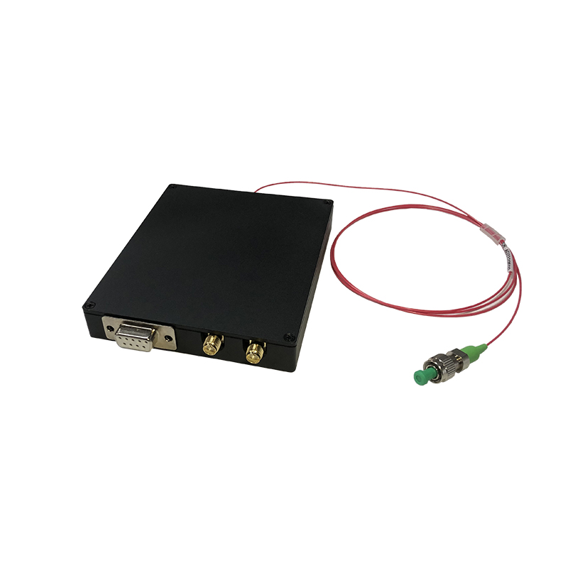
The GY-LASER-T-C series of tunable lasers developed by our company adopts the current national leading calibration technology, and through a series of processes of independent research and development, experiments, production, and testing, it realizes high-speed and high-precision controllable laser output; moreover, for the convenience of use, this series adopts the standard RS232 interface, and can be connected and controlled by using only the standard RS232 communication cable; in addition, this laser In addition, the laser provides point synchronization and frame synchronization signals, according to the starting wavelength and scanning step of the starting laser, combined with the point synchronization and frame synchronization signals, the current wavelength can be easily and quickly calculated.
Features:
- Continuously adjustable wavelength, the smallest step of 1pm, to achieve 41000 points of independent output
- High wavelength accuracy, using the international highest precision calibration instrument calibration, the highest accuracy of ± 0.3pm
- High power output, up to 13dBm
- Fast scanning speed, under 10pm step size, the fastest 1s to complete the C-band scanning
- Simple communication interface, using the standard RS232 interface
- Easy to use control software
Applications:
- Optical Device Testing
- FBG Fiber Grating Sensor Measurement
- Laser Scanning Spectrum Analysis
Parameter :
Params Value wavelength range 1527-1568nm
scanning speed
1Hz:40nm/s(@10pm step),100Hz/1000Hz/2000Hz optional
scanning step
≥1pm
Absolute wavelength accuracy
±1pm(typical value),±0.3pm(optimum value)
Wavelength Repeatability
±0.3pm
wavelength stability
±0.3pm
Output optical power
13dBm
Power Stability
±0.05dBm
Side mode rejection ratio
≥45dB
relative intensity noise
-135dB/Hz
line width
1MHz
operating voltage
4.5~5.5
power wastage
2W
operating temperature
-15~55℃
Storage temperature
-40~80℃
Dimension L*W*H
120*80*15.6mm
Module Dimensions
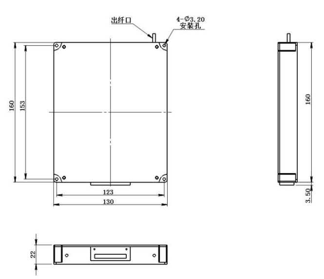
Instructions for use
1、Hardware interface

- Power Supply Connector
- The hardware interface is 8pin (as shown above), Pin1 and 2 are the power supply interface.
- The light source is powered by a 5V DC power supply with a voltage range of 4.5~5.5V, which may cause the module to fail to operate normally or even be damaged.
- communication interface
- Pin4, 5 and 6 are the RS232 receiving, transmitting and signal ground interfaces respectively.
- Using the RS232-USB interface cable provided by our company, the RS232 terminal is connected according to the pin order, and the USB terminal is directly connected to the computer, which is convenient for wiring.
- Synchronous Signal Interface
- Pin7 and 8 are the frame synchronization and point synchronization signals of the light source respectively.
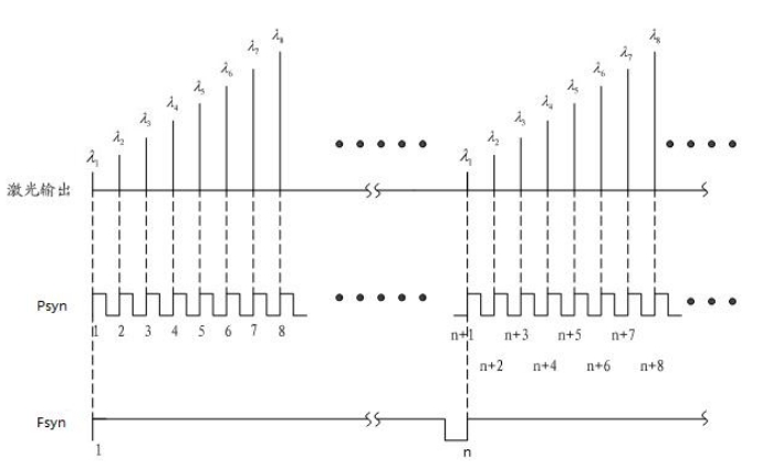
- As shown in the figure, the laser has a synchronized frame synchronization signal with a synchronized rising edge output at the beginning of each wavelength cycle scanning, and at the same time, the point synchronization signal has a synchronized rising edge signal output at the beginning of each wavelength output. This allows the user to count the point synchronization signal at the beginning of the frame synchronization rising edge, and then calculate the current wavelength based on the starting wavelength and step information, which is convenient and accurate.
2、Optical interface
Optical interface fiber diameter, connector, pigtail length can be selected, convenient for customers to choose according to the system, in addition, the fiber outlet is protected by a soft hose to avoid the risk of pigtail breakage, which effectively improves the service life of the scanning laser light source.
3、Software use
In accordance with the introduction of the hardware interface and optical interface connected to the light source, the system power on the power supply module began to work and self-check whether the voltage is normal, TEC temperature control temperature stabilization, to be stabilized after the temperature into the software control, software control is described below:
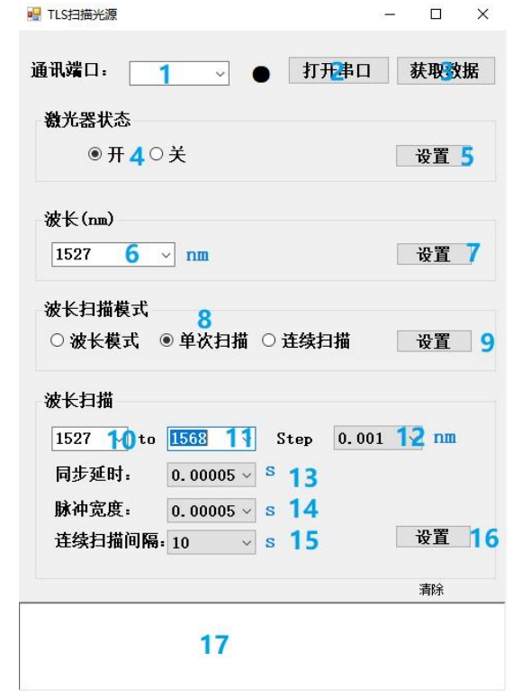
Basic Settings: When you use it, you need to 1 select the corresponding serial port of the scanning laser light source, click 2 to open the serial port, click 3 to get the data to test the serial port communication, if the communication is successful, it will show communication success in 17, if not, you need to check the hardware connection; after the communication is successful, the laser status will select on in 4, then click on the settings to take effect;
Wavelength Mode: In this mode, the scanning laser light source always outputs a single wavelength of laser light. 8 select the wavelength mode and click button 9 to take effect. 6 select or enter the wavelength and click button 7 to get the laser light of the desired wavelength;
Single Scan: In this mode, the scanning laser light source scans once from the set start wavelength to the end wavelength according to the step size. 8 select the single scan mode, click button 9 to make it effective, 10 select the start wavelength, 11 select the end wavelength, 12 select the step size, 13 set the synchronization delay (the synchronization delay is the interval between two different wavelengths), 14 set the pulse width (the pulse width is the duration of a single wavelength), 14 set the pulse width (the pulse width is the duration of a single wavelength), 14 set the pulse width (the pulse width is the duration of a single wavelength). Pulse width (pulse width is the duration of a single wavelength), 15 set the continuous scanning interval (continuous scanning interval is the time interval between two scanning cycles), click button 16, scanning the laser light source to carry out a cycle scan;
Continuous scanning: In this mode, the scanning laser light source scans continuously from the set start wavelength to the termination wavelength according to the step size. 8 select continuous scanning mode, click button 9 to take effect, 10 select the start wavelength, 11 select the termination wavelength, 12 select the step size, 13 set the synchronization delay (the synchronization delay is the time interval between two different wavelengths), 14 set the pulse width (the pulse width is the duration of a single wavelength), 14 set the pulse width (the pulse width is the duration of a single wavelength). Pulse width (pulse width is the duration of a single wavelength), 15 set the continuous scanning interval (continuous scanning interval is the time interval between two scanning cycles), click button 16, scanning the laser light source can be carried out continuous cycle scanning.
Tunable lasers are lasers in which the wavelength of the laser output can be continuously varied within a certain range. These lasers are used in a wide range of applications, including spectroscopy, photochemistry, medicine, biology, integrated optics, pollution monitoring, semiconductor material processing, information processing and communications.
Product Description:
The GY-LASER-T-C series of tunable lasers developed by our company adopts the current national leading calibration technology, and through a series of processes of independent research and development, experiments, production, and testing, it realizes high-speed and high-precision controllable laser output; moreover, for the convenience of use, this series adopts the standard RS232 interface, and can be connected and controlled by using only the standard RS232 communication cable; in addition, this laser In addition, the laser provides point synchronization and frame synchronization signals, according to the starting wavelength and scanning step of the starting laser, combined with the point synchronization and frame synchronization signals, the current wavelength can be easily and quickly calculated.
Features:
- Continuously adjustable wavelength, the smallest step of 1pm, to achieve 41000 points of independent output
- High wavelength accuracy, using the international highest precision calibration instrument calibration, the highest accuracy of ± 0.3pm
- High power output, up to 13dBm
- Fast scanning speed, under 10pm step size, the fastest 1s to complete the C-band scanning
- Simple communication interface, using the standard RS232 interface
- Easy to use control software
Applications:
- Optical Device Testing
- FBG Fiber Grating Sensor Measurement
- Laser Scanning Spectrum Analysis
Parameter :
| Params | Value |
|---|---|
| wavelength range | 1527-1568nm |
| scanning speed | 1Hz:40nm/s(@10pm step),100Hz/1000Hz/2000Hz optional |
| scanning step | ≥1pm |
| Absolute wavelength accuracy | ±1pm(typical value),±0.3pm(optimum value) |
| Wavelength Repeatability | ±0.3pm |
| wavelength stability | ±0.3pm |
| Output optical power | 13dBm |
| Power Stability | ±0.05dBm |
| Side mode rejection ratio | ≥45dB |
| relative intensity noise | -135dB/Hz |
| line width | 1MHz |
| operating voltage | 4.5~5.5 |
| power wastage | 2W |
| operating temperature | -15~55℃ |
| Storage temperature | -40~80℃ |
| Dimension L*W*H | 120*80*15.6mm |
Module Dimensions

Instructions for use
1、Hardware interface

- Power Supply Connector
- The hardware interface is 8pin (as shown above), Pin1 and 2 are the power supply interface.
- The light source is powered by a 5V DC power supply with a voltage range of 4.5~5.5V, which may cause the module to fail to operate normally or even be damaged.
- communication interface
- Pin4, 5 and 6 are the RS232 receiving, transmitting and signal ground interfaces respectively.
- Using the RS232-USB interface cable provided by our company, the RS232 terminal is connected according to the pin order, and the USB terminal is directly connected to the computer, which is convenient for wiring.
- Synchronous Signal Interface
- Pin7 and 8 are the frame synchronization and point synchronization signals of the light source respectively.

- As shown in the figure, the laser has a synchronized frame synchronization signal with a synchronized rising edge output at the beginning of each wavelength cycle scanning, and at the same time, the point synchronization signal has a synchronized rising edge signal output at the beginning of each wavelength output. This allows the user to count the point synchronization signal at the beginning of the frame synchronization rising edge, and then calculate the current wavelength based on the starting wavelength and step information, which is convenient and accurate.
- Pin7 and 8 are the frame synchronization and point synchronization signals of the light source respectively.
2、Optical interface
Optical interface fiber diameter, connector, pigtail length can be selected, convenient for customers to choose according to the system, in addition, the fiber outlet is protected by a soft hose to avoid the risk of pigtail breakage, which effectively improves the service life of the scanning laser light source.
3、Software use
In accordance with the introduction of the hardware interface and optical interface connected to the light source, the system power on the power supply module began to work and self-check whether the voltage is normal, TEC temperature control temperature stabilization, to be stabilized after the temperature into the software control, software control is described below:

Basic Settings: When you use it, you need to 1 select the corresponding serial port of the scanning laser light source, click 2 to open the serial port, click 3 to get the data to test the serial port communication, if the communication is successful, it will show communication success in 17, if not, you need to check the hardware connection; after the communication is successful, the laser status will select on in 4, then click on the settings to take effect;
Wavelength Mode: In this mode, the scanning laser light source always outputs a single wavelength of laser light. 8 select the wavelength mode and click button 9 to take effect. 6 select or enter the wavelength and click button 7 to get the laser light of the desired wavelength;
Single Scan: In this mode, the scanning laser light source scans once from the set start wavelength to the end wavelength according to the step size. 8 select the single scan mode, click button 9 to make it effective, 10 select the start wavelength, 11 select the end wavelength, 12 select the step size, 13 set the synchronization delay (the synchronization delay is the interval between two different wavelengths), 14 set the pulse width (the pulse width is the duration of a single wavelength), 14 set the pulse width (the pulse width is the duration of a single wavelength), 14 set the pulse width (the pulse width is the duration of a single wavelength). Pulse width (pulse width is the duration of a single wavelength), 15 set the continuous scanning interval (continuous scanning interval is the time interval between two scanning cycles), click button 16, scanning the laser light source to carry out a cycle scan;
Continuous scanning: In this mode, the scanning laser light source scans continuously from the set start wavelength to the termination wavelength according to the step size. 8 select continuous scanning mode, click button 9 to take effect, 10 select the start wavelength, 11 select the termination wavelength, 12 select the step size, 13 set the synchronization delay (the synchronization delay is the time interval between two different wavelengths), 14 set the pulse width (the pulse width is the duration of a single wavelength), 14 set the pulse width (the pulse width is the duration of a single wavelength). Pulse width (pulse width is the duration of a single wavelength), 15 set the continuous scanning interval (continuous scanning interval is the time interval between two scanning cycles), click button 16, scanning the laser light source can be carried out continuous cycle scanning.
